Polymer electrolyte fuel battery
A fuel cell and electrolyte technology, which is used in solid electrolyte fuel cells, fuel cells, and fuel cell components, etc., can solve the problems of reduced power generation efficiency and increased power consumption of fuel cell systems.
- Summary
- Abstract
- Description
- Claims
- Application Information
AI Technical Summary
Problems solved by technology
Method used
Image

Examples
no. 1 example
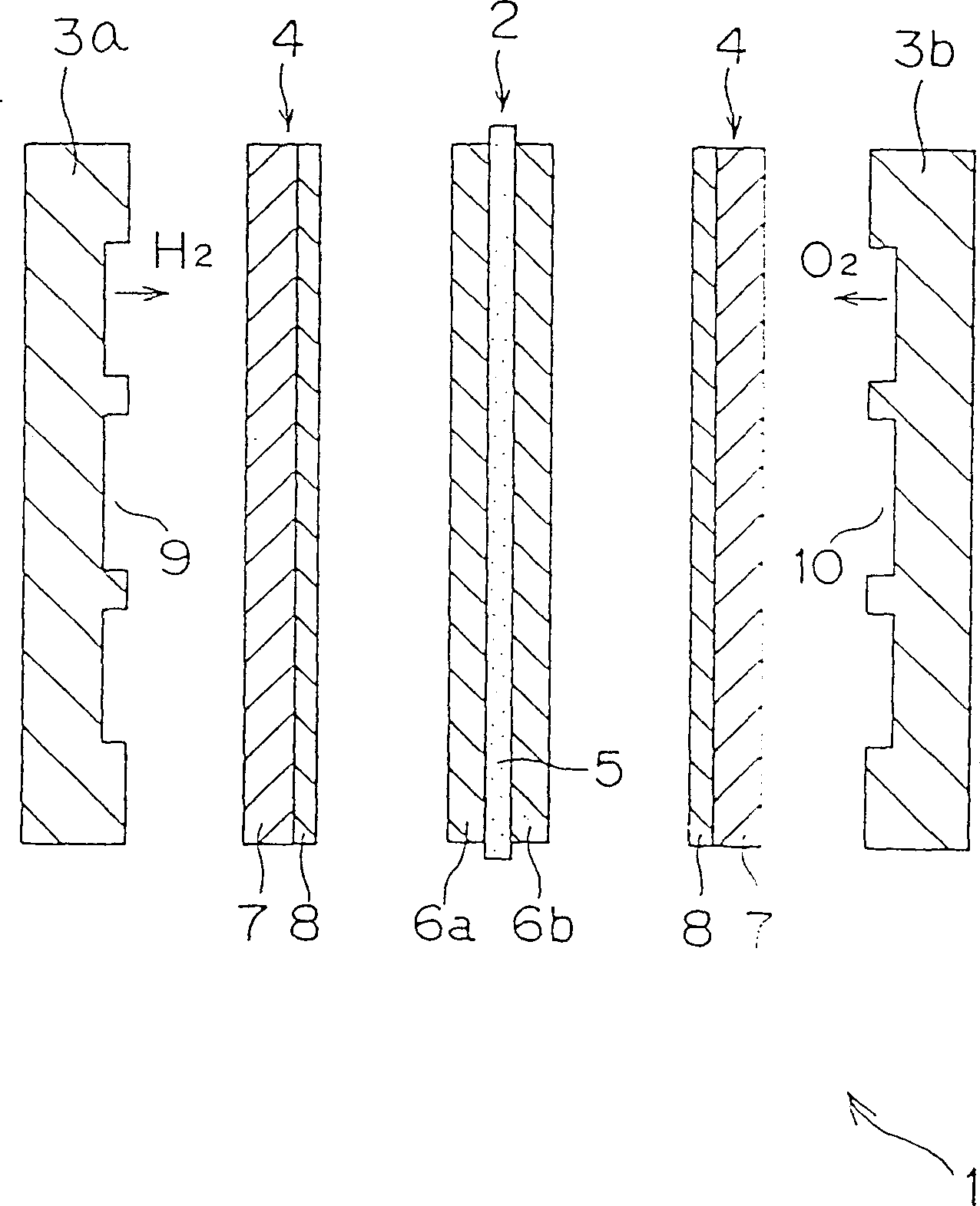
[0031] figure 1 is an exploded sectional view illustrating a polymer electrolyte fuel cell according to an embodiment of the present invention. This fuel cell 1 is composed of a battery unit 2, separators 3a, 3b arranged on both sides of the battery unit 2 so that the battery unit 2 is inserted between them, and separators 3a, 3b arranged between the above-mentioned battery unit 2 and the separators 3a, 3b. Diffusion layer 4 composition.
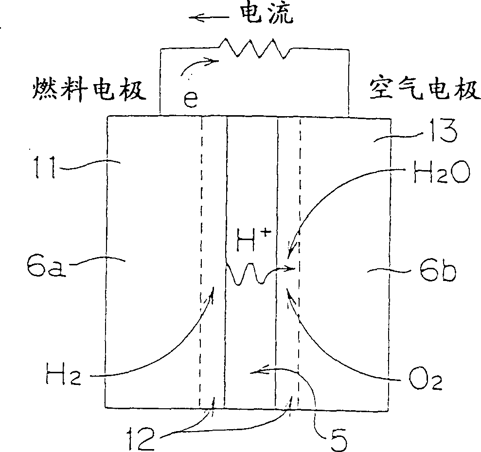
[0032] The battery 2 described above consists of a solid polymer membrane 5 with reaction layers 6a, 6b arranged on both sides of the membrane 5 .
[0033] The solid polymer membrane 5 is, for example, a membrane formed of perfluorosulfonic acid.
[0034] Each of the above-mentioned diffusion layers 4 is composed of a carbon paper 7, also called a substrate, and a slip layer 8 formed on one of its main surfaces. This carbon paper can be replaced by another conductive porous material such as carbon cloth or non-woven carbon fiber. The sli...
no. 2 example
[0048] see now Figure 5 . Figure 5 is a schematic sectional view of a diffusion layer and a separator constituting a PEFC according to a second embodiment of the present invention. In this embodiment, the partition 25 has a protruding portion 26 having a greater thickness than its surroundings. Corresponding to this protruding portion 26, the carbon paper 27 has a compression layer (gas barrier) 28 formed so as to be concave than its surroundings. A slip layer 8 is formed on the above-mentioned carbon paper 27 having the above-mentioned compressed layer 28 .
[0049] Therefore, according to the second embodiment, the convex portion 26 having a larger thickness than its periphery is formed on a predetermined position of the separator 25, and the compression layer 28 corresponding to the convex portion 26 is formed on the carbon paper 27. As a result, like the first embodiment, water retention in the battery can be prevented and uniform power generation can be obtained over...
no. 3 example
[0051] see now Figure 6 . Figure 6 is a schematic sectional view of a diffusion layer constituting a PEFC according to a third embodiment of the present invention. In this embodiment, the gas barrier includes a resin-impregnated layer 31 formed by impregnating a resin into a portion of carbon paper (substrate) 21 intended for gas barrier formation. This resin-impregnated layer 31 is airtight and does not allow gas to pass through. A slip layer 8 is formed on the carbon paper 27 having the resin-impregnated layer 31 described above.
[0052] Therefore, according to the third embodiment, the resin-impregnated layer 31 having airtightness is formed in the portion of the carbon paper 21 intended for gas barrier formation. As a result, like the first embodiment, water retention in the battery can be prevented and uniform power generation can be obtained over the entire surface of the battery. Furthermore, a uniform gas flow rate can be obtained over the entire surface of the ...
PUM
| Property | Measurement | Unit |
|---|---|---|
| porosity | aaaaa | aaaaa |
| porosity | aaaaa | aaaaa |
Abstract
Description
Claims
Application Information
 - R&D
- Intellectual Property
- Life Sciences
- Materials
- Tech Scout
- Unparalleled Data Quality
- Higher Quality Content
- 60% Fewer Hallucinations
Browse by: Latest US Patents, China's latest patents, Technical Efficacy Thesaurus, Application Domain, Technology Topic, Popular Technical Reports.
© 2025 PatSnap. All rights reserved.Legal|Privacy policy|Modern Slavery Act Transparency Statement|Sitemap|About US| Contact US: help@patsnap.com