Hole taking method for sheet metal part

A technology of sheet metal parts and parts, which is applied in aircraft parts, transportation and packaging, etc., can solve the problems of strength impact and affect the structural strength of parts, and achieve the effect of ensuring the strength requirements

Active Publication Date: 2022-03-01
HARBIN
View PDF5 Cites 0 Cited by
  • Summary
  • Abstract
  • Description
  • Claims
  • Application Information

AI Technical Summary

Problems solved by technology

[0003] For the forming of existing large and complex parts with many lightening holes, the traditional method generally adopts the method of requiring the design of the inner hole on the part as the process hole. Using this process method, although the forming accuracy of the part can be guaranteed, the process hole will be Finally retained on the part, it will inevitably have a certain impact on its strength
There are many such parts in the fairing section of a certain type of machine. In view of the fact that the forming of such parts requires at least three pin inner holes to be positioned on the mold, it is possible to ensure that the parts will not be "pulled" during the forming process to conform to the part mold. The acceptance requirements of the cutting line, so too many pin inner holes are set, which can easily affect the structural strength of the part

Method used


Image

  • Hole taking method for sheet metal part
  • Hole taking method for sheet metal part
  • Hole taking method for sheet metal part

Examples


Embodiment 1

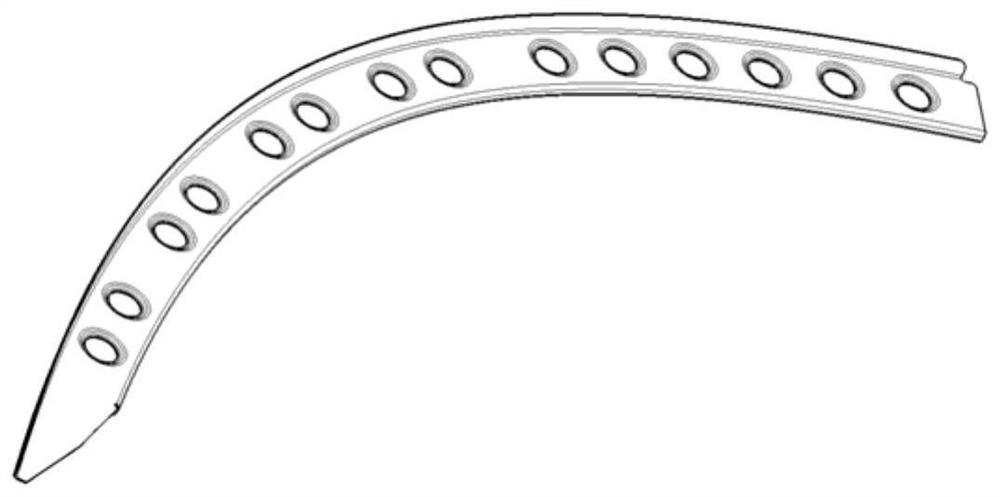
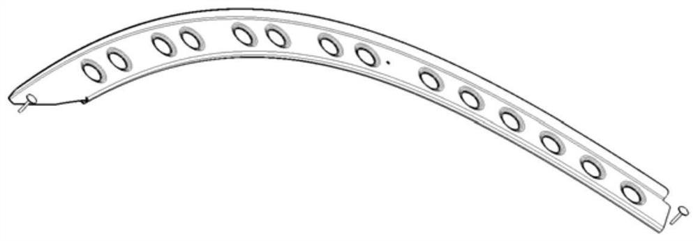
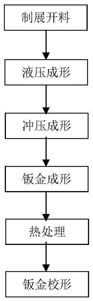
[0039] by figure 1 The part shown is taken as an example to explain the forming process of the part in detail, please refer to figure 2 , the status diagram of the position of the positioning hole of the part before the improvement, the part structure of this embodiment is simple, and the lightening holes are arranged in an arrangement structure. Through the unique hole design, the present invention selects the inner hole of the pin on the large part, and finally flushes it out as a process hole to avoid remaining on the part. At the same time, the strength requirement of the design can be fully guaranteed after the part is formed. See the process for details. image 3 :

[0040] (1) Manufacture of unfolded materials

[0041] Calculate the size of the unfolded material according to the specific part. At the same time, the size of the reference hole of the fifth lightening hole from the left of the part is required to be Φ6. This hole is used for the positioning of the part ...

Embodiment 2

[0053] This embodiment is similar to embodiment 1, adopts similar parts to carry out hole extraction, just selects the lightening hole of different position as reference hole to carry out hole extraction, process is as follows:

[0054] (1) Manufacture of unfolded materials

[0055] Calculate the size of the unfolded material according to the specific part, and at the same time require the reference hole size of the 8th lightening hole from the left of the part to be Φ6. This hole is used for positioning the part in the hydroforming process to prevent the part from being "pulled" during the forming process. At the same time, it is used for The positioning of the thimble of the punching die for the relief hole in the stamping process is to improve the precision of punching the relief hole, and the remaining relief holes are Φ20.

[0056] (2) Hydroforming

[0057] This step is more critical and is the basis of the follow-up process. Two sets of molds are required for forming. ...


PUM


Abstract

The invention belongs to a sheet metal machining technology, and particularly relates to a sheet metal part hole taking method. According to specific parts, the size of an unfolded blank is calculated, and blanking is carried out; a phi m hole is formed in the first pressing plate at the position of the other lightening hole according to the requirement of the first set of pattern die, and a phi n hole mgt is formed in the position of the lightening hole determined in the first step; n; a punching die is used for punching a phi n hole of a part, and the phi n hole in the part is used for positioning a punching die ejector pin when a lightening hole is punched. The pin inner hole can be prevented from being reserved in the part, and although the pin inner hole is located in the outline of the part, the auxiliary hole can be punched away finally through a punching scheme. By adopting the process method, the process hole can be prevented from being finally reserved in the part, and meanwhile, the designed strength requirement can be completely met after the part is formed.

Description

technical field [0001] The invention belongs to the sheet metal processing technology, and in particular relates to a hole-taking method for a sheet metal part. Background technique [0002] In the manufacture of large parts, due to design requirements, it is necessary to design and select a large number of relief holes, and the selection and size design of relief holes will inevitably affect the structural strength of the part itself. [0003] For the forming of existing large and complex parts with many lightening holes, the traditional method generally adopts the method of requiring the design of the inner hole on the part as the process hole. Using this process method, although the forming accuracy of the part can be guaranteed, the process hole will be Ultimately retained on the part, it will inevitably have a certain impact on its strength. There are many such parts in the fairing section of a certain type of machine. In view of the fact that the forming of such parts...

Claims


Application Information

Patent Timeline
Patent Type & Authority Applications(China)
IPC IPC(8): B21D53/92B21D28/26B21D35/00B23P15/00
CPCB21D53/92B21D35/001B21D28/26B23P15/00Y02P10/25
Inventor 李宗奕温可黄兴
Owner HARBIN
Why Eureka
Try Eureka