Electric vacuum cleaner
A vacuum cleaner, electric technology, applied in the direction of vacuum cleaners, suction filters, cleaning equipment, etc., can solve problems such as paper bag electric vacuum cleaners, scattered dust, etc., to achieve waste dust saving trouble and hygiene, reduce the drop of suction air volume, simple structure Effect
- Summary
- Abstract
- Description
- Claims
- Application Information
AI Technical Summary
Problems solved by technology
Method used
Image
Examples
Embodiment 1
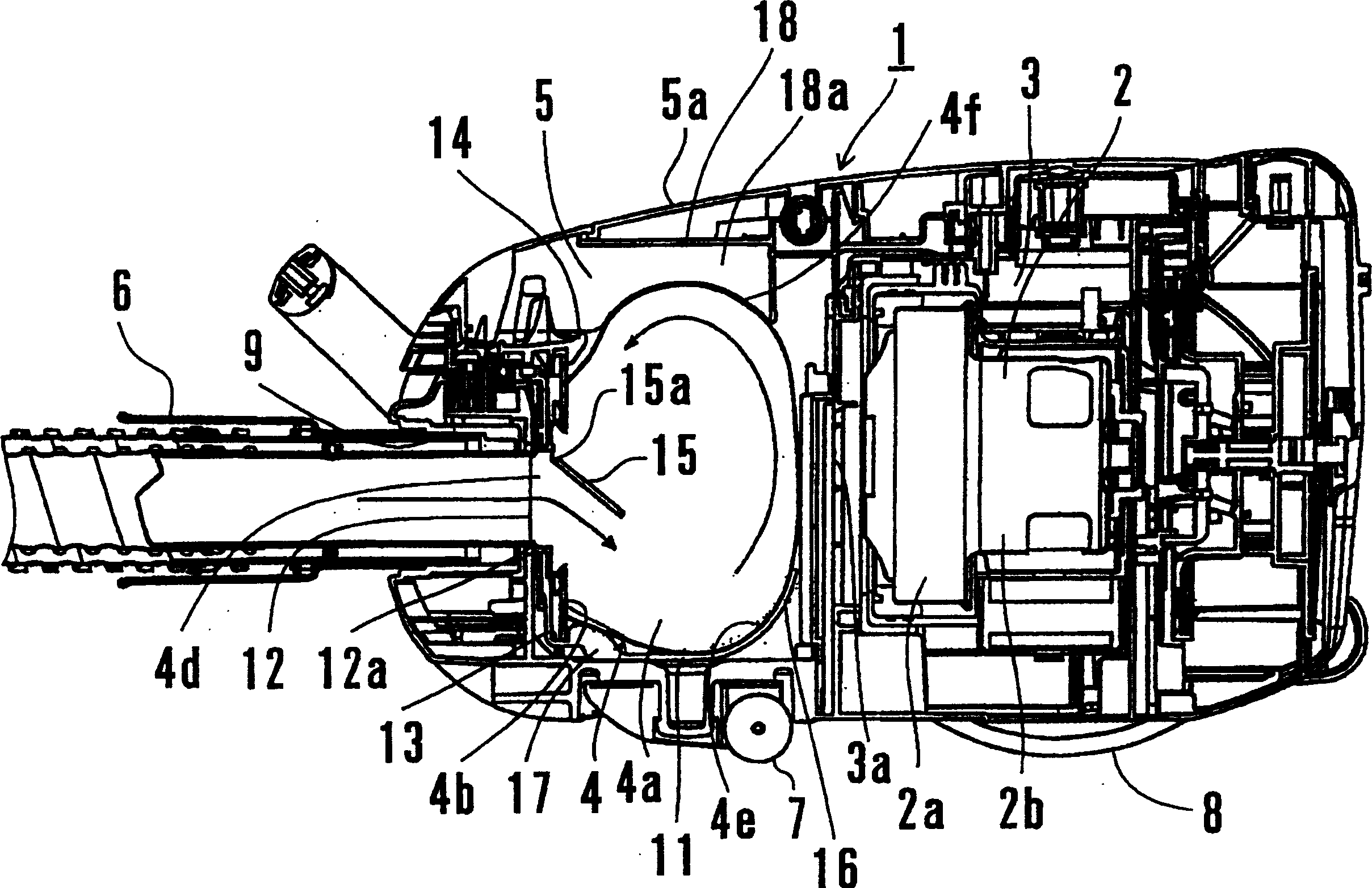
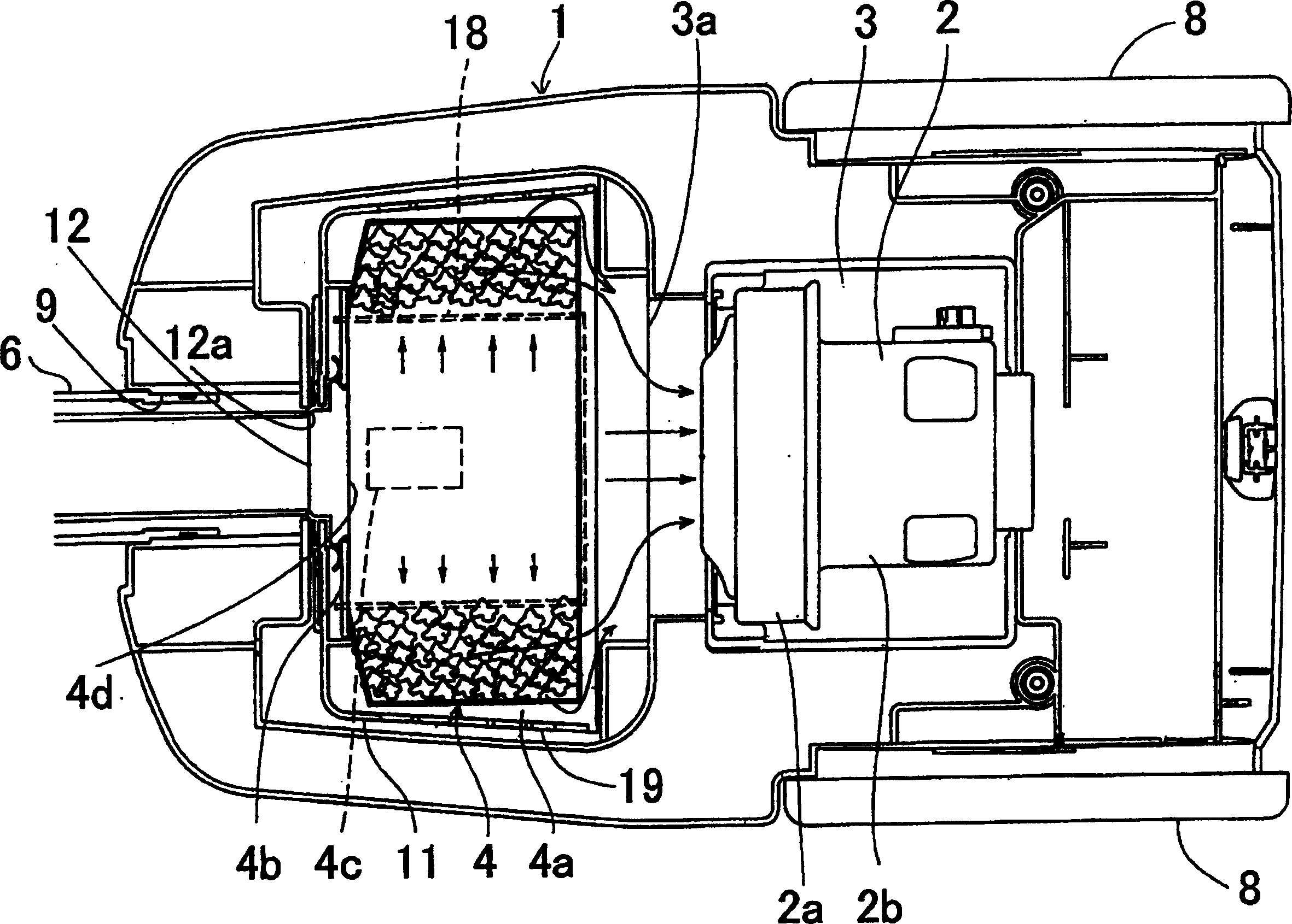
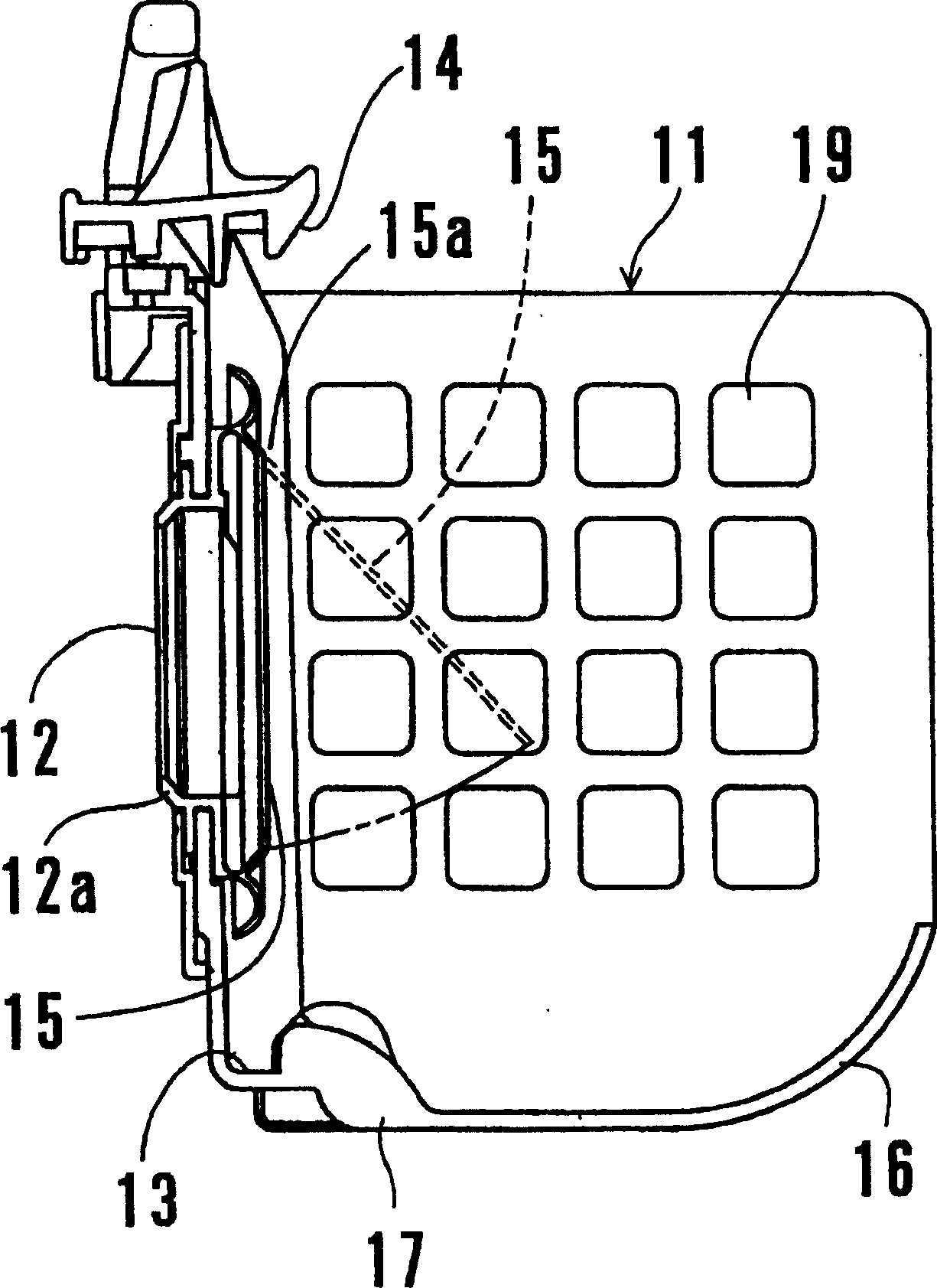
[0056] figure 1 It is a side sectional view of a return type electric vacuum cleaner according to Embodiment 1 of the present invention, figure 2 yes means figure 1 The top sectional view of the general structure of the electric vacuum cleaner, image 3 Yes figure 1 Side cutaway view of the basket of an electric vacuum cleaner.
[0057] The electric vacuum cleaner shown in these drawings has a motor chamber 3 with an electric blower 2 built in, a paper bag 4 disposed in front of the motor chamber 3, and a dust collection chamber 5 for storing the paper bag 4 in the interior of the vacuum cleaner main body 1, and the front end is connected to a The floor suction hose 6 etc. which are not shown in figure are comprised.
[0058] On the upper part of the vacuum cleaner main body 1, an upper cover 5a for opening and closing the dust collection chamber 5 and enabling easy replacement of the paper bag 4 is provided. Moreover, the front wheel 7 and the rear wheel 8 for moving th...
Embodiment 2
[0086] The following is based on the attached Figure 4 Example 2 will be described. Figure 4 It is a side sectional view of the return type electric vacuum cleaner of Example 2.
[0087] In Embodiment 2, as shown in the figure, the auxiliary rib 18 supporting the lower front part of the paper bag 4 in Embodiment 1 is made into a curved support wall 21 continuous with the curved support wall 16 forming the first shape maintaining member. In addition, in this second embodiment, the auxiliary ribs 22 in the front-rear direction are formed instead of the auxiliary ribs 18 below the upper cover 5 a in the first embodiment. In addition, the rear portion 22a of the auxiliary rib 22 functions as a second shape maintaining member instead of the auxiliary rib 18a in the first embodiment.
[0088] Also, other structures are the same as in Embodiment 1, in Figure 4 In , the same symbols are used for the parts that are common to Example 1.
[0089] Therefore, although Embodiment 2 d...
Embodiment 3
[0091] The following is based on Figure 5 Example 3 will be described. Figure 5 It is a side sectional view of the return type electric vacuum cleaner of Example 3.
[0092] like Figure 5 As shown, in Embodiment 3, the curved surface support wall 16 forming the first shape-maintaining member in Embodiment 1 is changed to the auxiliary rib 31 formed on the bottom surface of the basket 11, and the supporting rib 31 under the front part of the paper bag 4 in Embodiment 1 is omitted. Auxiliary ribs17. In this third embodiment, like the second embodiment, the auxiliary ribs 22 in the front and rear directions are formed instead of the auxiliary ribs 18 below the upper cover 5a in the first embodiment. In addition, the rear portion 22a of the auxiliary rib 22 functions as a second shape maintaining member instead of the auxiliary rib 18a in the first embodiment.
[0093] In addition, other structures are the same as in Embodiment 1, in Figure 5 In , the same symbols are giv...
PUM
 Abstract
Description
Claims
Application Information
 - R&D
- Intellectual Property
- Life Sciences
- Materials
- Tech Scout
- Unparalleled Data Quality
- Higher Quality Content
- 60% Fewer Hallucinations
Browse by: Latest US Patents, China's latest patents, Technical Efficacy Thesaurus, Application Domain, Technology Topic, Popular Technical Reports.
© 2025 PatSnap. All rights reserved.Legal|Privacy policy|Modern Slavery Act Transparency Statement|Sitemap|About US| Contact US: help@patsnap.com


