Ozonated liquid dispensing unit

a liquid dispensing unit and ozonated technology, applied in the direction of liquid chemical processes, liquid gas reaction processes of thin film type, gas-gas reaction processes, etc., can solve the problems of difficult maintenance of systems, increased equipment and supply costs, and poor cleaning and sanitizing, etc., to achieve convenient installation

Active Publication Date: 2015-11-03
CLEANCORE SOLUTIONS LLC
View PDF138 Cites 44 Cited by
  • Summary
  • Abstract
  • Description
  • Claims
  • Application Information

AI Technical Summary

Benefits of technology

[0006]An ozonated liquid dispensing unit is described herein. The unit produces and dispenses an ozonated liquid that may be used to clean and sanitize a variety of articles or used in conjunction with cleaning processes and other apparatus. The unit is compact, may be conveniently installed in a commercial or residential kitchen, restroom or other area with a water supply. The units provides an ozonated liquid with a high concentration of ozone gas sufficient to clean and sanitize food items, food preparation items, food preparation surface, bathrooms, medical equipment, drains and to provide for hand-washing and hygiene needs. The unit uses multiple dielectric cells in an in-line configuration to create the ozone gas that is mixed with the water to form the ozonated liquid. A first dielectric cell prepares ozone gas that is supplied to a second dielectric cell, which creates additional ozone gas, thus creating a highly concentrated supply of ozone gas that is supplied to an injector.
[0007]Foods, food preparation areas as well as other surfaces that may benefit from sterilization provided by the unit. In the food industry, the ozonated liquid from the unit provides for chemical-free sterilization of contaminated surfaces and tools, such as those used in the processing of raw meat. The ozonated liquid cleans toxic substances 3,000 times faster than chlorine, and unlike chlorine, ozonated liquid is completely safe and natural. The ozonated liquid kills micro-organisms, including E. coli, salmonella, bacteria, viruses, molds, etc. The ozonated liquid also remove pesticides and other residues from fruits and vegetables. The ozonated liquid also reduces odors in the environment on which the ozonated liquid is sprayed. The unit is ideal for residential food preparation, commercial food preparation, or any place a sterile, cleaning solution is needed. In a commercial setting, fruits and vegetables may be washed with the unit and its ozonated liquid to increase the shelf-life of the items. By removing the micro-organisms from the surfaces of the fruit and vegetables that may cause decay and spoilage, the fruit and vegetables will not decay or spoil as fast.
[0009]The unit is easy to install. Generally, the unit is just plugged into an electrical unit and a water supply is provided to the unit. The unit discharges the ozonated liquid into a liquid supply line in fluidic communication with a sprayer or faucet. A handle, knob or other actuator is manipulated in order to begin the production and flow of ozonated liquid from the unit.
[0010]Ozone gas is unstable, which provides for it cleaning and sanitizing capabilities, but also makes consistent ozone levels difficult to maintain when the gas is mixed into a solution. Ozone gas cannot be packaged or stored and must be generated on site. The unit reduces the need for chemicals, hot water, and labor. Conventional cleaning systems often require the use of warm or hot water, which may form condensation in the surrounding workspace. This condensation may provide for or encourage the growth of microorganisms. Because unit only uses cold water, condensation is less likely to form in the surrounding workspace. The unit also reduces the hydraulic load on the waste-water treatment system and eliminates the need to treat the chemicals that would be present in conventional wastewater discharge streams.
[0013]In other aspects, a reaction vessel for processing an ozonated fluid is provided. The reaction vessel includes an assembly, which includes a fluid entry opening to receive an ozonated fluid and a fluid exit opening to discharge the ozonated fluid. The reaction vessel further includes a container, and the assembly engages the container. The container holds a core. The container is in fluidic communication with the fluid entry opening and the fluid exit opening. The ozonated fluid passes into and out of an annulus between the core and the container. The reaction vessel processes the ozonated fluid to reduce the bubble size of the ozone gas in the ozonated fluid and to reduce the number of ozone gas bubbles in the ozonated fluid to increase the concentration of ozone in the ozonated fluid.

Problems solved by technology

Prior attempts to provide an ozonated liquid in a kitchen environment have failed to provide an ozonated liquid with sufficient concentrations of ozone resulting in poor cleaning and sanitizing.
Without sufficient ozone concentration, conventional cleaning and sanitizing methods may still be necessary at extra labor, equipment, and supply costs.
Such systems are difficult to maintain.
Such systems are often too large and too bulky to be effectively used in some residential or commercial applications.
Many of these systems are also too expensive for use in the home or are not economical to be used in commercial applications.
Such systems often require significant mechanical alterations to existing water supply and delivery systems.
Further, many previous systems cannot be used with multiple, different dispensing applications.

Method used


Image

  • Ozonated liquid dispensing unit
  • Ozonated liquid dispensing unit
  • Ozonated liquid dispensing unit

Examples


Embodiment Construction

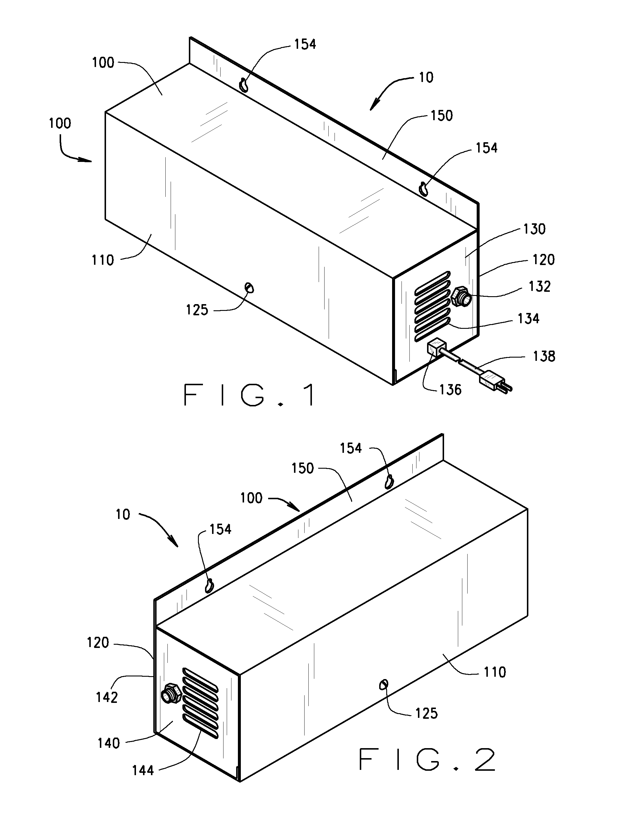
[0036]An ozonated liquid dispensing unit is described herein. With reference to FIGS. 1 and 2, an ozonated liquid dispensing unit 10 is shown. The unit 10 includes a housing 100, a removable housing cover 110 and a housing support 120. The housing 100, the housing cover 110, and the housing support 120 form a rectangular, box-like structure that houses the internal components of the unit 10. The housing 100 may be designed or engineered in other shapes and configurations. The housing 100, the housing cover 110, and the housing support 120 are made from sturdy or rugged materials, such as stainless steel, aluminum, or metals. Plastics and other composite materials may also be utilized in the construction of the housing 100, the housing cover 110 and the housing support 120.

[0037]As shown in FIGS. 4-6, the housing cover 110 is removed from the housing 100 to show the housing support 120, which receives and stabilizes the internal components of the unit 10. The housing cover 110 may be...


PUM

PropertyMeasurementUnit
sizeaaaaaaaaaa
open volumeaaaaaaaaaa
volumeaaaaaaaaaa

Abstract

A ozonated liquid dispensing unit is described. The unit produces and dispenses an ozonated liquid that may be used to clean and sanitize a variety of articles or used in conjunction with cleaning processes and other apparatus. The unit includes a liquid input port to receive liquid into the unit. The unit includes a first dielectric cell for producing ozone gas from ambient air and a second dielectric cell for producing ozone gas. The first dielectric cell is in supply communication with the second dielectric cell for supplying the second dielectric cell with a supply gas containing the ozone gas generated from the ambient air. The second dielectric cell produces ozone gas from the supply gas. An injector is in fluidic communication with the liquid input port. The injector in supply communication with the second dielectric cell for receiving the ozone gas from the second dielectric cell, and the injector mixes the ozone gas from the second dielectric cell with the liquid from the liquid input port to produce an ozonated liquid. A liquid output port discharges the ozonated liquid from the unit. A faucet or spray may be used to control the discharge of the ozonated liquid from the unit.

Description

CROSS REFERENCE TO RELATED APPLICATION[0001]This application is a continuation-in-part of U.S. Nonprovisional patent application Ser. No. 12 / 179,335 filed Jul. 24, 2008, which is hereby incorporated by reference.FIELD OF INVENTION[0002]The present invention relates to an ozonated liquid dispensing unit that produces and dispenses an ozonated liquid that may be used to clean and sanitize a variety of articles or used in conjunction with cleaning processes and other apparatus.BACKGROUND OF INVENTION[0003]Prior attempts to provide an ozonated liquid in a kitchen environment have failed to provide an ozonated liquid with sufficient concentrations of ozone resulting in poor cleaning and sanitizing. Without sufficient ozone concentration, conventional cleaning and sanitizing methods may still be necessary at extra labor, equipment, and supply costs.[0004]Other prior attempts to provide an ozonated liquid have involved electrochemical ozone generation. Such systems are difficult to maintai...

Claims


Application Information

Patent Timeline
Patent Type & Authority Patents(United States)
IPC IPC(8): C01B13/11A23B7/157C11D3/50B01F3/04A23B7/158C11D3/39A61L2/18B01F23/00
CPCC01B13/11A23B7/157A23B7/158A61L2/183B01F3/04744B01F3/04836C11D3/39C11D3/50A23V2002/00A61L2/18B01F2003/04886C01B2201/32C01B2201/40C01B2201/62C01B2201/64A23V2200/10A23V2250/128B01F23/23411B01F23/2368B01F23/237613
Inventor LYNN, DANIEL W.
Owner CLEANCORE SOLUTIONS LLC
Why Eureka
Try Eureka