
Distributor for exhaust gas turbine with axial flow

An exhaust gas turbine, axial flow technology, applied in the direction of engine components, machines/engines, mechanical equipment, etc., can solve the problems of components stuck and self-locking, etc., to achieve simple adjustment force, simple and reliable guide vane adjustment, and work reliability. high effect

Inactive Publication Date: 2007-03-14
ABB (SCHWEIZ) AG
View PDF6 Cites 3 Cited by
  • Summary
  • Abstract
  • Description
  • Claims
  • Application Information

AI Technical Summary

Problems solved by technology

Due to the high forces that have to be transmitted during the adjustment of the adjusting ring, this construction presents the risk of parts jamming and self-locking

Method used


Image

  • Distributor for exhaust gas turbine with axial flow
  • Distributor for exhaust gas turbine with axial flow
  • Distributor for exhaust gas turbine with axial flow

Examples


Embodiment Construction

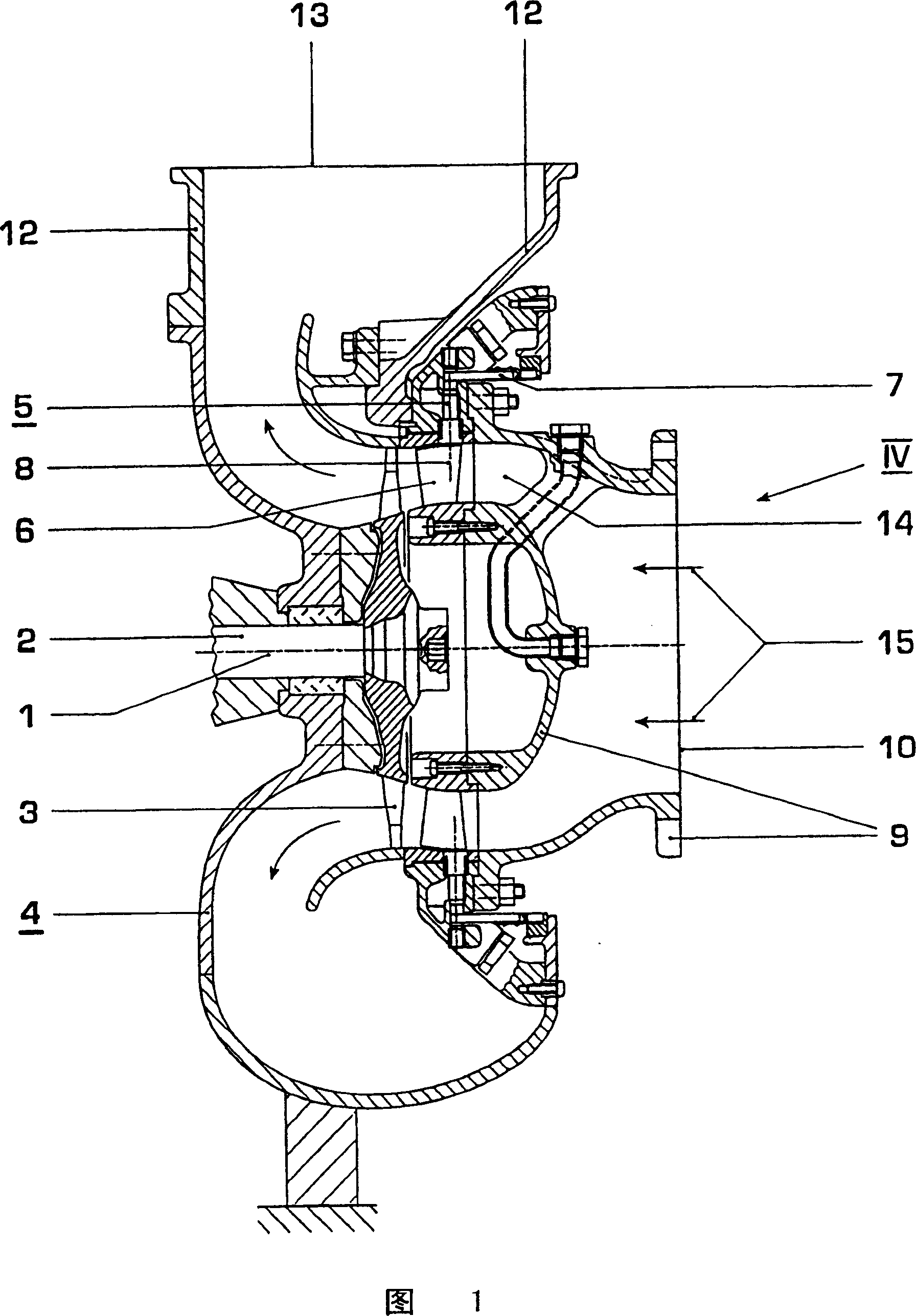
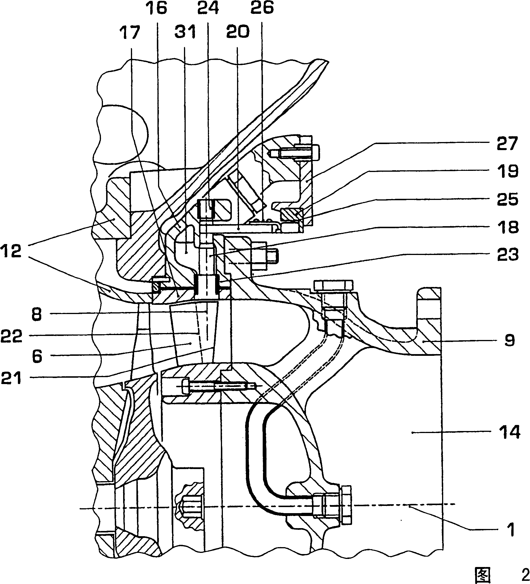
[0019] In all figures, the same symbols refer to parts having the same function. FIG. 1 shows only the turbine part of the exhaust gas turbocharger with the exhaust gas turbine. The exhaust gas turbine has a rotor 2 rotatable about an axis 1 with a turbine wheel and rotor blades 3 fastened thereto, as well as a turbine housing 4 and an axisymmetrically arranged rotor with adjustable guide vanes 6 to the turbine axis 1 ring and a spout 5 of a rotating device 7. By rotating them about a radially extending axis 8 , the guide vanes 6 can each be pivoted into any angular position between two end positions.

[0020] The rotor 2 leads airtight from the turbine housing 4 to a bearing point (not shown) and is mounted on the left-hand end in FIG. 1 with a compressor wheel, not shown in FIG. 1 .

[0021] The turbine housing 4 comprises an inlet housing 9 with an axisymmetrically arranged inlet 10 and an outlet housing 12 with a radially oriented outlet 13 . A flow channel 14 defined b...


PUM


Abstract

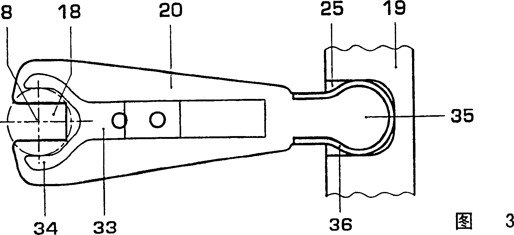
The conducting apparatus is for the position alteration of conducting blades (6) in a turbocharger exhaust gas turbine flowed through axially. The blades are arranged axially symmetrically to the turbine axis (1) in an exhaust gas flow channel (14) and can be pivoted by a pivot device around a radially fitted axis (8). To each blade is fitted a shaft (18) which extends through a housing wall radially outwards from the flow channel. This shaft with its outwardly extending part is rotatably located around a pivot axis (8). The pivot device contains a positioning ring (19) rotatable around the turbine axis and positioning levers (20) transmit torque from the positioning ring to the shaft of each blade.

Description

technical field [0001] The invention relates to a nozzle which is connected upstream of an axial exhaust gas turbine and which has guide vanes arranged axisymmetrically to the turbine axis and which are each rotatable about a radially extending axis in a flow channel through which the exhaust gas is conveyed, and A rotary device adjusts the guide vane about the axis of rotation. In the case of such nozzles, the size of the cross-sectional area of ​​the flow channel through which the exhaust gas flows can be changed by rotating the guide vanes and the exhaust gas turbine can be adapted in a particularly advantageous manner to the changing exhaust gas flow conditions itself, as Occurs during part-load operation of an internal combustion engine supplying exhaust gases. Background technique [0002] Such a spout is described, for example, in EP0131719 B1 and especially in the embodiment according to FIGS. 3-5 . Arranged coaxially to the turbine wheel in the nozzle opening is a...

Claims


Application Information

Patent Timeline
Patent Type & Authority Patents(China)
IPC IPC(8): F01D17/16F02B39/00F01D25/24F02B37/24
CPCF01D17/162F05D2220/40F05B2220/40F05D2250/33F05B2250/33F01D17/16
Inventor D·贝伦德特J·贝茨M·赛勒
Owner ABB (SCHWEIZ) AG
Learn More