
Pipe joint

A technology for tubes and female joints, applied in the direction of engine components, liquid fuel feeders, machines/engines, etc., can solve problems such as incorrect assembly, lengthening of the retainer, and lengthening of the housing 15

Inactive Publication Date: 2007-05-30
SANOH IND CO LTD
View PDF4 Cites 0 Cited by
  • Summary
  • Abstract
  • Description
  • Claims
  • Application Information

AI Technical Summary

Problems solved by technology

The problem that exists in this case is: retainer 16 becomes long, and shell 15 becomes long
However, as a customer, there is a problem that the retainer 16 needs to be pulled out, changed to the correct direction for assembly, and a new operation is required.
[0028] In addition, as shown in Fig. 15 (b) dashed-two dotted line, the possibility that exists also has: the retainer 16 comes from the side of the hole 19a on the opposite side, that is, from the side of the horizontal edge portion 16b without the notch 37. Wrong assembly of assembly holder 16

Method used


Image

  • Pipe joint
  • Pipe joint
  • Pipe joint

Examples


Embodiment Construction

[0049] Hereinafter, the pipe joint of the present invention will be described in detail with reference to the drawings.

[0050] 1st form of implementation

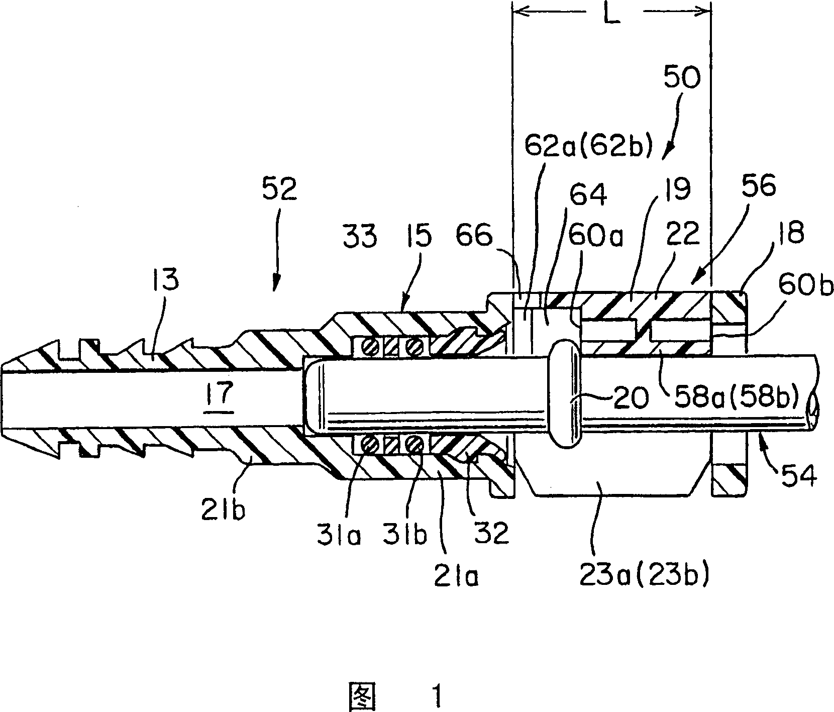
[0051] Fig. 1 is a longitudinal sectional view showing a pipe joint according to a first embodiment of the present invention. The female joint member 52, male joint member 54, and retainer 56 constituting the pipe joint 50 of the first embodiment are the same as the female joint member 12 and male joint member 14 of the conventional quick connector shown in FIGS. 9 and 10 . , The retainer 16 has members having the same constituent elements, and the same reference numerals are used for the same constituent elements to omit the detailed description thereof, and the different parts will be described in detail below.

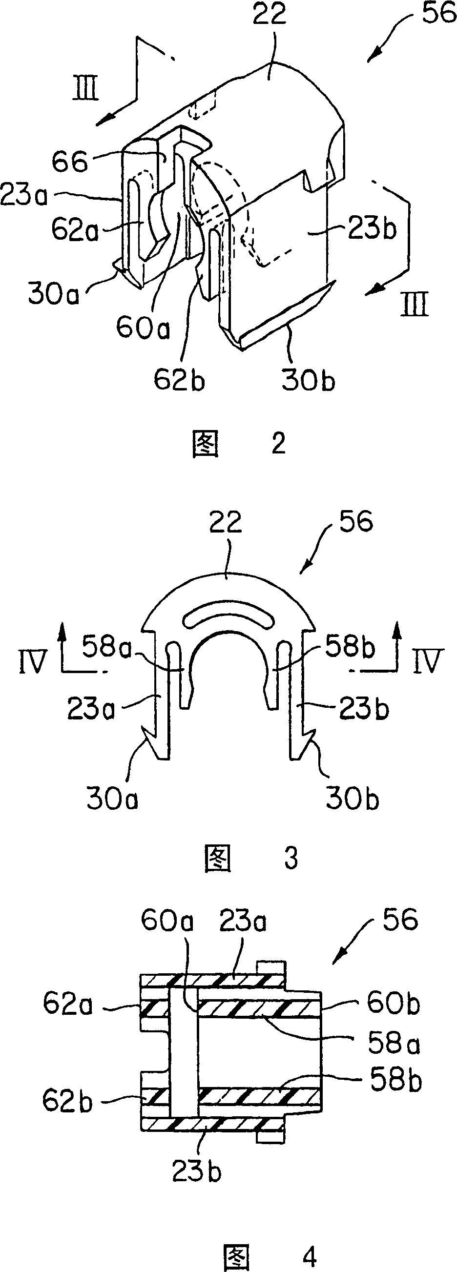
[0052] As shown in FIGS. 2 and 3 , the holder 56 is an integrally formed plastic U-shaped member, and the main body 22 of the holder 56 has legs 23a, 23b extending parallel to both sides. Inside the legs 23a,...


PUM


Abstract

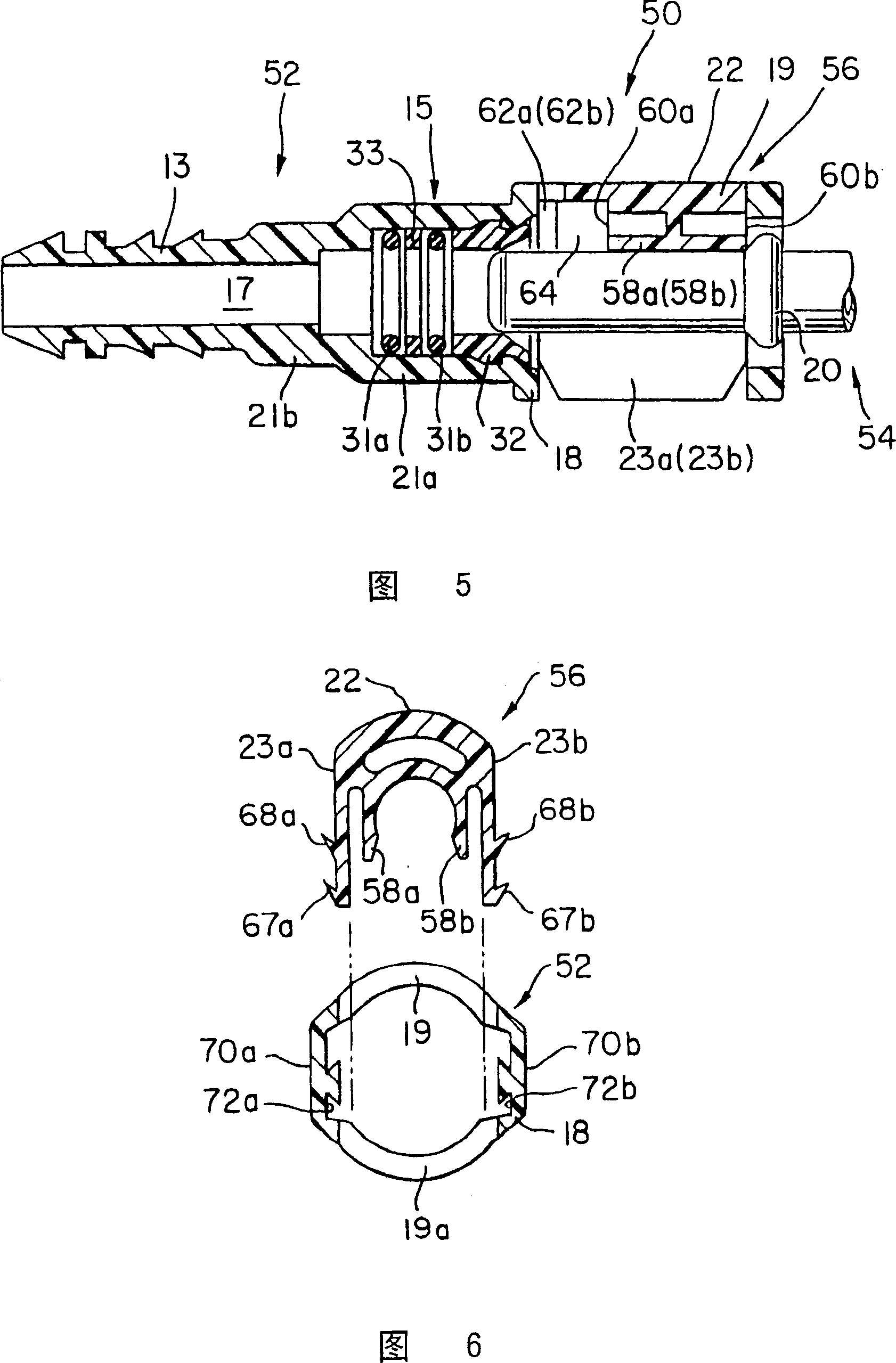
A pipe joint having a construction such that when a retainer is pseudo-locked, it is clearly shown that the female and male joint members are in an incomplete joined state, the joint having a high pressure resisting strength. The joint comprises a first rib (58a, 58b) having a first end edge (60a) on one end side that, when a retainer (56) is pushed in with a male joint member (54) completely inserted in a female joint member (52), engages the spool portion (20) of the male joint member (54) to prevent backward axial movement of the male joint member (54), and a second end edge (60b) on the other end side, the first rib being formed on the inner side of the leg portion (23a, 23b) of the retainer (56), a second rib (62a, 62b) spaced from the first end edge of the first rib by an amount corresponding to at least the width of the spool portion (20), the second rib abutting against a presser member (32) fitted in a passageway in the female joint member so as to prevent release of O-rings (31a, 31b) disposed in the female joint member, thereby controlling axial movement of the presser member (32).

Description

technical field [0001] The present invention relates to a pipe joint, and more particularly to a quick connector type pipe joint used for connecting pipes in a fluid circuit of a mechanical device or the like. Background technique [0002] For example, in a fuel supply system of an automobile, a joint called a quick connector is widely used as a pipe joint for connecting a fuel pipe. [0003] The main components of the quick connector are: a female joint part and a male joint part that are respectively installed on the pipe to be connected, and a retainer that connects them. The quick connector does not use connecting elements such as bolts, and only needs to insert the male joint part into the female joint part, and the pipes can be easily connected in one operation. [0004] For such quick connectors, various structures have been proposed so far. As the required function of the quick connector, the connection should be firm and the disassembly should be simple, but in ot...

Claims


Application Information

Patent Timeline
Patent Type & Authority Patents(China)
IPC IPC(8): F16L37/14F02M37/00
CPCF16L37/144
Inventor 冈田宏幸赤木正纪
Owner SANOH IND CO LTD
Learn More