
Ink jet print apparatus and ink jet print method

An inkjet printing device and printing head technology, applied in printing devices, printing, instruments, etc., can solve the problems of insufficient effect and the like

Inactive Publication Date: 2007-07-18
CANON KK
View PDF13 Cites 2 Cited by
  • Summary
  • Abstract
  • Description
  • Claims
  • Application Information

AI Technical Summary

Problems solved by technology

However, there are many cases where the interpolated part becomes conspicuous according to the conventional method described above.
That is, in the conventional non-row interpolation processing, it is still in an insufficient state in terms of obtaining its effect.

Method used


Image

  • Ink jet print apparatus and ink jet print method
  • Ink jet print apparatus and ink jet print method
  • Ink jet print apparatus and ink jet print method

Examples


no. 1 Embodiment approach

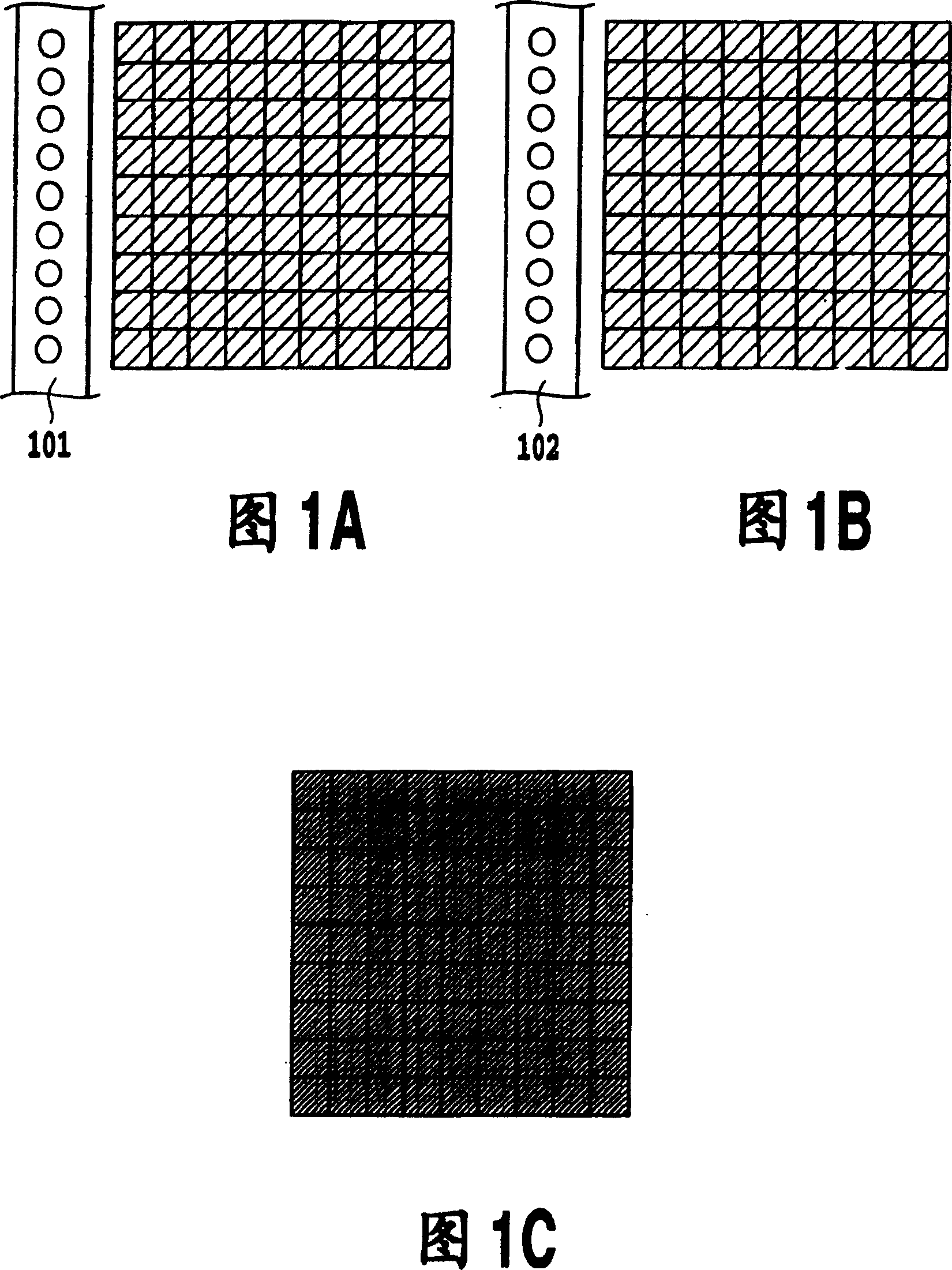
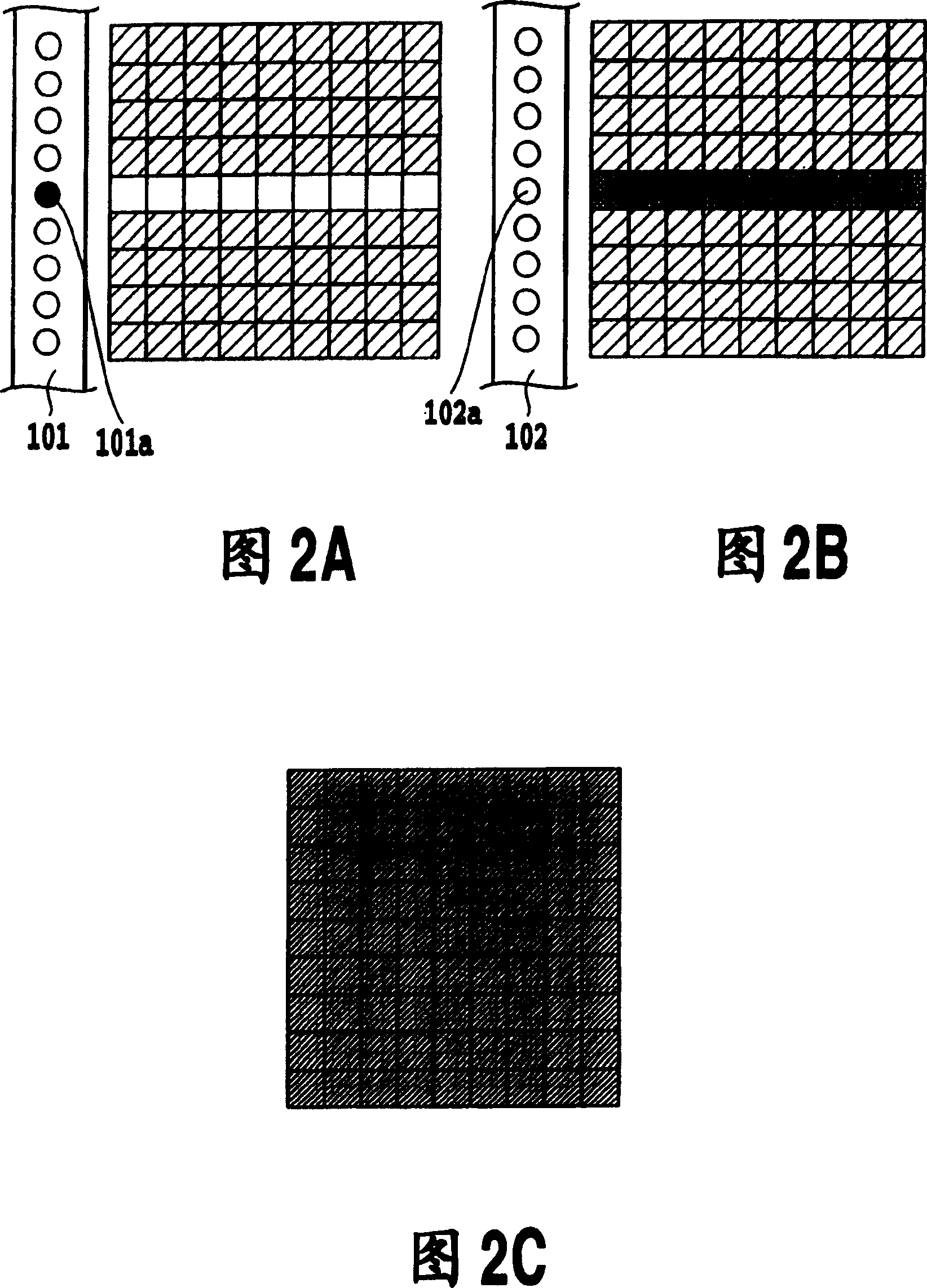
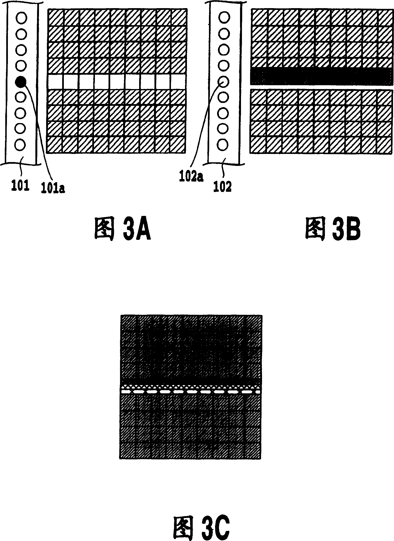
[0064] 8A to 8C are diagrams for explaining the interpolation method in the first embodiment of the present invention. Similar to FIGS. 3A to 3C , FIGS. 8A to 8C show printing states in which 25% of the image data is printed using the nozzle group 101 and the nozzle group 102 including the defective nozzle 101 a and non-row interpolation processing is performed. Here, when the printing device is a serial type, the direction of the arrow is the main scanning direction of the print head, and when the printing device is a line type, the direction of the arrow is the conveying direction of the printing medium.

[0065]In the non-row interpolation processing in FIGS. 3A to 3C , only the data of the pixels printed by the defective nozzle 101 a are extracted and added to the data of the pixels printed by the defective nozzle 102 a. On the other hand, in this embodiment, not only the pixel corresponding to 101a but also the pixels corresponding to the nozzles 101b and 101c adjacent to...

no. 2 Embodiment approach

[0112] Next, a second embodiment of the present invention will be described.

[0113] 11A-11C are diagrams for explaining the non-row interpolation method in this embodiment. FIGS. 11A to 11C also show the printing state in the case where 25% of the data is printed with the nozzle group 101 and the nozzle group 102 including the defective nozzle 101a and the non-row interpolation process is performed. When the printing device is a serial type, the direction of the arrow is the main scanning direction of the print head, and when the printing device is a line type, the direction of the arrow is the conveyance direction of the printing medium.

[0114] In the non-row interpolation in the first embodiment, the data of the pixel at a predetermined position among the pixels printed by the defective nozzle 101a and the nozzles on both sides thereof is reduced, and the corresponding value is added to the corresponding value of the replacement nozzle 102a and the two sides thereof. on...

no. 3 Embodiment approach

[0125] Next, a third embodiment of the present invention will be described. In the above-mentioned two embodiments, the method of performing data exchange (subtraction and addition) of image data in a multi-valued state has been described. Furthermore, instead of setting the basic density value (data) to 0 for the pixels near the defective nozzle, subtraction is performed at a predetermined ratio, and the corresponding density value (data) is added to the pixel near the replacement nozzle. On the other hand, in the non-sequence interpolation processing of this embodiment, it is determined to perform after converting whether or not the image data is to be sequenced into clear binary information. Therefore, the data is set to 0 also for the pixels near the defective nozzle, and the data is moved as it is to the pixel near the replacement nozzle.

[0126] 12A-12D are diagrams for explaining the correction method in this embodiment. FIG. 12A is the binary image data printed by t...


PUM


Abstract

In an image area printed by a nozzle group including a defective nozzle, pixels printed by the defective nozzle and part of pixels located in the vicinity of the same are printed by another nozzle group. As a result, since printing is performed not only at the pixels printed by the defective nozzle but also at the pixels in the neighborhood thereof simultaneously by separate nozzles, irregularities of printing attributable to interpolation are distributed even when there is a relative misalignment between the nozzle groups. It is therefore possible to obtain a preferable image without any decrease in output time even when a printing head including a defective nozzle is used.

Description

technical field [0001] The present invention relates to an inkjet printing device and a printing method capable of eliminating image blurring caused by defective nozzle discharge and realizing high-speed printing. Background technique [0002] In recent years, in the fields of printers, facsimile machines, copiers, and the like, printing apparatuses using the inkjet method have been provided in many cases. In particular, a color inkjet printing device that prints a color image using multi-color inks is rapidly spreading because of its effect on expressing images of high image quality. [0003] In such inkjet printing, it can be mainly classified into serial printing and line printing. Serial printing alternately repeats the print main scan in which a print head having a plurality of recording elements scans and prints a print medium, and the sub scan in which the print medium is conveyed in a direction intersecting the print main scan, thereby to form an image. Therefore,...

Claims


Application Information

Patent Timeline
Patent Type & Authority Patents(China)
IPC IPC(8): B41J2/07G06F17/00B41J2/01B41J2/165B41J2/21B41J29/393
CPCB41J2/2139B41J29/393
Inventor 柴田烈小板桥规文八岛正孝
Owner CANON KK
Learn More