
Scheduler for a shared channel

A technology for sharing channels and user stations, which is applied in the field of scheduling data and can solve problems such as capacity waste

Inactive Publication Date: 2007-08-01
SOMA NETWORKS INC
View PDF5 Cites 0 Cited by
  • Summary
  • Abstract
  • Description
  • Claims
  • Application Information

AI Technical Summary

Problems solved by technology

Also, since each time slot carries data traffic for a single subscriber station, some capacity of the time slot is likely to be wasted due to internal splitting

Method used


Image

  • Scheduler for a shared channel
  • Scheduler for a shared channel
  • Scheduler for a shared channel

Examples


Embodiment Construction

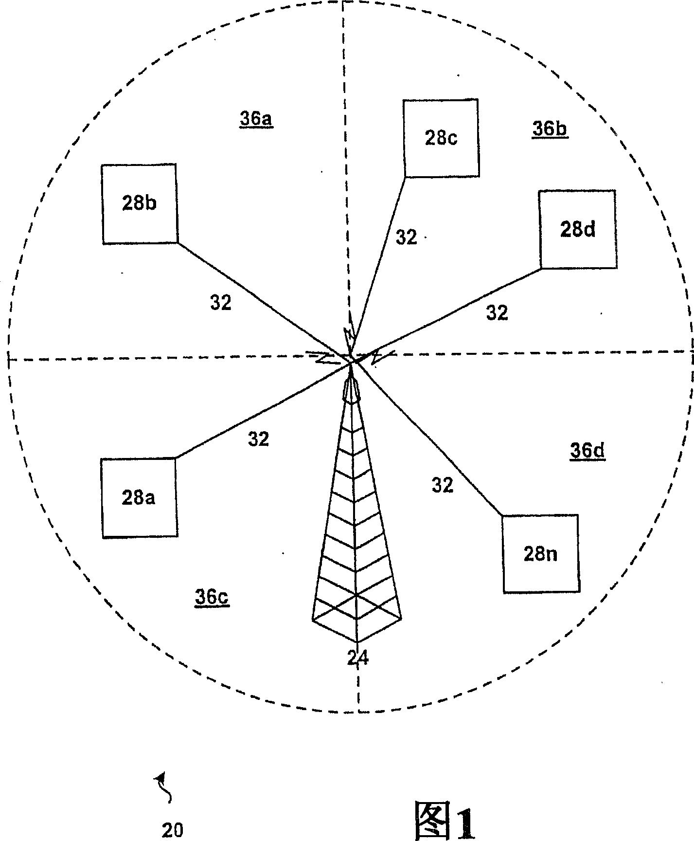
[0028] Referring now to FIG. 1 , a wireless network for transmitting data is indicated generally at 20 . The network 20 includes a radio base station 24 and a plurality of subscriber stations 28a, 28b...28n. In the presently preferred embodiment, radio base station 24 passes through a suitable gateway and one or more backhauls (not shown), such as T1, T3, E1, E3, OC3 or other suitable landline links, or satellite or other A radio or microwave channel link, or any other link suitable for operation as a backhaul as occurs to those skilled in the art, connected to at least one data telecommunications network

[0029] (not shown), such as a landline based data switching network, a packet network, or the like.

[0030] The base station 24 communicates with a subscriber station 28, which may be a stationary device, a nomadic device, or a mobile device. The number "n" of subscriber stations serviced by base station 24 may vary depending on the amount of radio bandwidth available an...


PUM


Abstract

A method, system and apparatus for scheduling data to subscriber stations from a base station over a shared channel. Data destined for each subscriber station is placed into queues at the base station. The base station allocates a portion of the shared channel to each particular queue based upon that queue's priority value. The priority value for each queue is determined by an adjusted QoS value and an adjusted throughput value. The QoS value indicates whether a subscriber station has been receiving data according to an agreed-upon QoS level. The throughput value indicates the data rate that can be achieved by transmitting to that subscriber station. These two values are examined by a scheduling policy at the base station. Scheduling policies can include scheduling data to emphasize fairness between subscriber stations, scheduling data to improve overall throughput, and scheduling data to achieve a balance between fairness and throughput.

Description

Background of the invention [0001] The invention relates to a system, method and device for scheduling data in a network. More particularly, the present invention relates to a system, method and apparatus for scheduling data traffic on a shared channel. Background of the invention [0002] In a network that includes a shared channel used to convey data traffic from a single transmitting station to multiple receiving stations, the transmitting station must determine how to allocate its downlink capacity among the receiving stations. Examples of such networks include CATV-based data networks and wireless networks, such as the AMOSPHERE® sold by the assignee of the present invention. TM system, etc. In the latter network, a base transceiver station will serve multiple subscriber stations over an air interface that provides both shared and dedicated downlink (base station to subscriber station) channels. Since the transmission capacity of the system is limited (typically by t...

Claims


Application Information

Patent Timeline
Patent Type & Authority Patents(China)
IPC IPC(8): H04L12/56H04Q7/20H04W28/22H04W72/04H04W72/12H04W84/08
CPCH04L47/2433H04L47/14H04L47/2416H04W72/1236H04W72/1242H04W84/08H04W28/22H04W72/1257H04W72/1252H04W28/02H04W72/543H04W72/52H04W72/569H04W72/535
Inventor 费萨尔·沙德
Owner SOMA NETWORKS INC
Learn More