Multi-hop packet radio networks

a packet radio and multi-hop technology, applied in the field of multi-hop packet radio networks, can solve the problems of remote stations in the network being restricted in their movement, controller nodes or base stations are relatively expensive, and the network is vulnerable to the breakdown of controllers or base stations

Inactive Publication Date: 2005-11-15
IWICS INC
View PDF9 Cites 144 Cited by
  • Summary
  • Abstract
  • Description
  • Claims
  • Application Information

AI Technical Summary

Benefits of technology

[0058]The processor means may also be operable to add or remove data selectively from the received data output to the selected one or more of the vocoders to control the rate at which a speech signal represented by the received data is replayed.

Problems solved by technology

Such networks are vulnerable to breakdown of the controller nodes or base stations.
In addition, the controller nodes or base stations are relatively expensive, and remote stations in the network are restricted in their movement with respect to the base stations.
The connectivity between stations in such a network may change due to relative movement between remote stations and the base station, interference, noise and other factors.
In a Rayleigh fading environment, the rate of fluctuation of signal strength, noise and interference changes the connectivity between stations in the network on an instantaneous basis, making any method of fixed routing or adaptive routing by the passing of routing information between stations almost impossible.
Generally, in order to compensate for interference and fading, messages are transmitted redundantly and with sufficient power to ensure their reception, leading to sub-optimal utilisation of the network and to interference between stations.

Method used


Image

  • Multi-hop packet radio networks
  • Multi-hop packet radio networks
  • Multi-hop packet radio networks

Examples


Embodiment Construction

[0076]The present invention has primary application in wireless data networks, including mobile radio or cellular telephone networks, two-way paging networks, meteor burst PCN data networks and low earth orbiting and geostationary satellite environments, where rapidly and greatly changing connectivity and platform population changes militate against the use of conventional networking techniques.

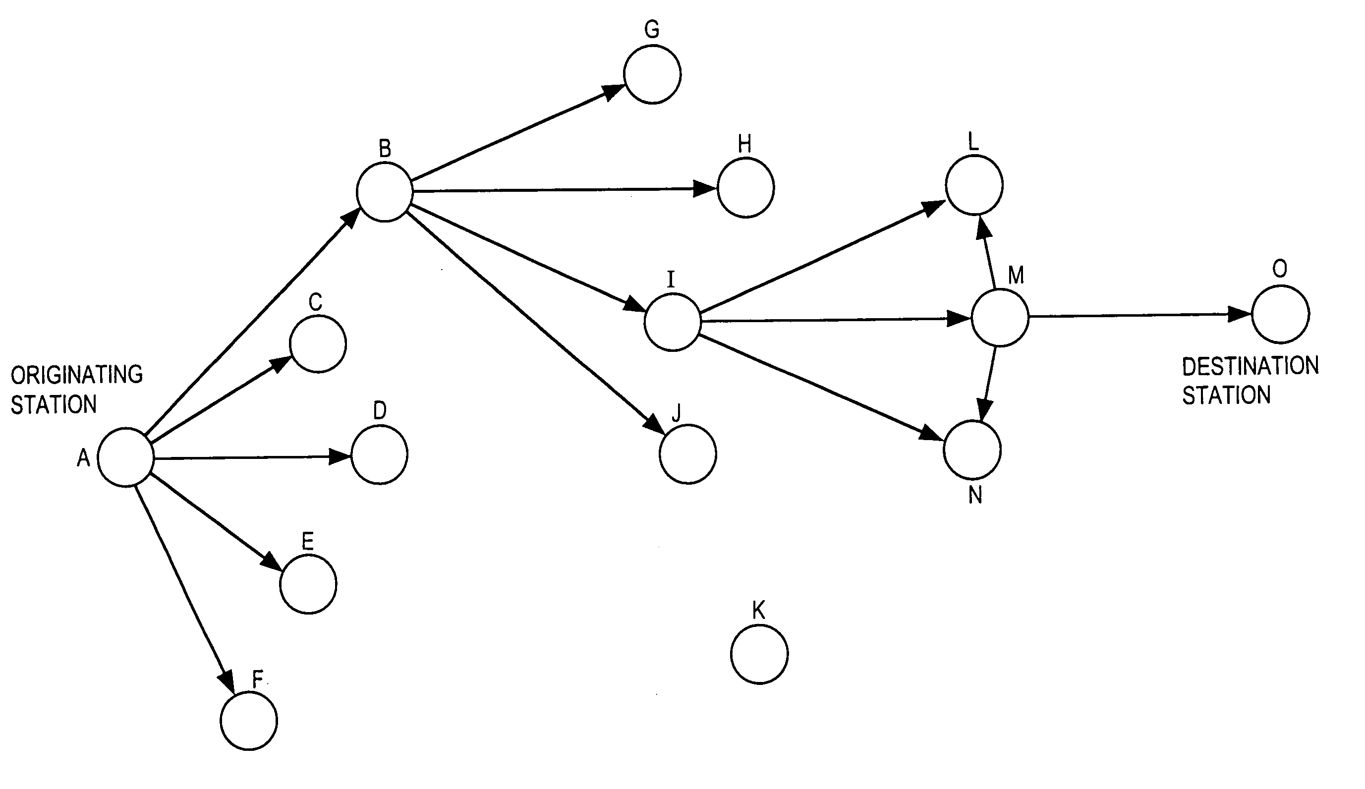
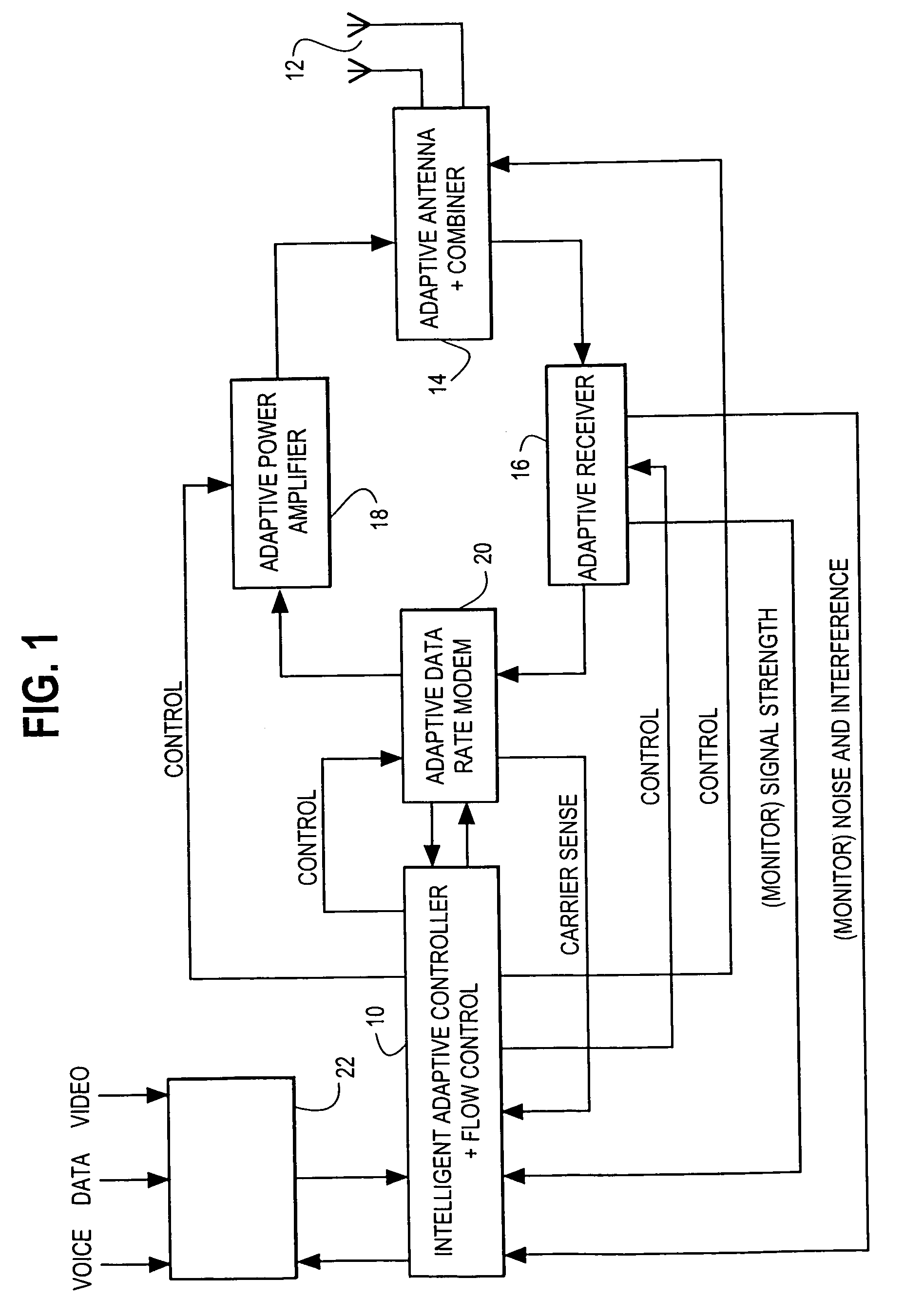
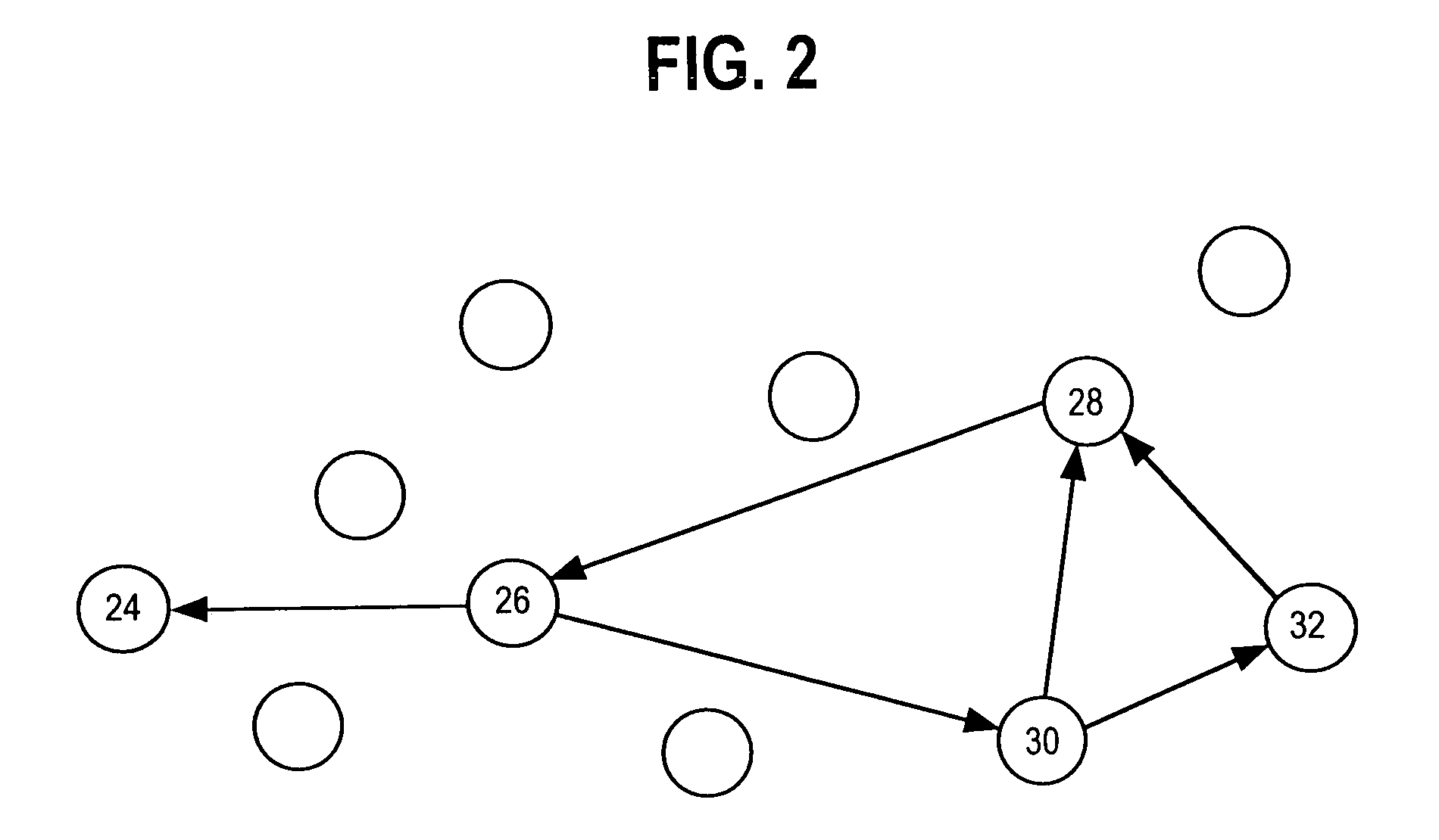
[0077]To this end, the invention provides a communication network which makes use of adaptive opportunistic communication between stations in the network. The network is a full mesh network which accommodates rapidly changing connectivity between stations and routes messages dynamically between stations on a co-operative basis to improve data throughput in the network, while minimizing power consumption and interference between stations. The invention optimises the network capacity by ensuring optimal utilisation of the available spectrum in terms of capacity (Erlangs) for a given area, a giv...


PUM


Abstract

An adaptive communication system utilises opportunistic peak-mode transmissions to transmit data between originating and destination stations, via one or more intermediate stations. Each station monitors the activity of other stations in the network, storing connectivity information for use in subsequent transmissions. Each station also sends out probe signals from time to time, to establish which other stations are in range. Messages are then sent across the network from station to station, with confirmation data being transmitted back to the originating station, until the destination station is reached. Old messages, which would otherwise clog the network, are timed out and deleted. A communication network and transceiver apparatus for use in the network are also disclosed.

Description

[0001]This application is a division of U.S. Ser. No. 08 / 849,875 (now U.S. Pat. No. 6,097,703) filed Jun. 18, 1997 and effectively filed Dec. 19, 1995, which is a U.S. National Completion of PCT / GB95 / 02972 filed Dec. 19, 1995, which applications are hereby incorporated herein by reference.BACKGROUND OF THE INVENTION[0002]THIS invention relates to a method of transmitting data between originating and destination stations in a multi-station communication network, to a communication network for implementing the method, and to communication apparatus for use in the network.[0003]Communication networks are known which require one or more controlling nodes or base stations through which messages must be routed from originating to destination stations. Such networks are vulnerable to breakdown of the controller nodes or base stations. In addition, the controller nodes or base stations are relatively expensive, and remote stations in the network are restricted in their movement with respect...

Claims


Application Information

Patent Timeline
Patent Type & Authority Patents(United States)
IPC IPC(8): H04L12/56H04B7/005H04W8/00H04W8/22H04B7/26H04W24/00H04W28/04H04W28/06H04W52/46H04W88/04
CPCH04W8/005H04W52/46H04W8/22H04W24/00H04W28/04H04W28/06H04W88/04H04W40/22Y02D30/70
Inventor LARSEN, MARK SIEVERT
Owner IWICS INC
Why Eureka
Try Eureka