Refrigerating storage cabinet

A technology for storage and cooling pipes, which is applied to household refrigeration devices, coolers, lighting and heating equipment, etc. It can solve problems such as high maintenance costs, inability to repair welding positions, and poor refrigeration, so as to improve reliability and inhibit freezing growth , the effect of easy operation

Inactive Publication Date: 2007-08-08
SANYO ELECTRIC CO LTD
View PDF1 Cites 0 Cited by
  • Summary
  • Abstract
  • Description
  • Claims
  • Application Information

AI Technical Summary

Problems solved by technology

[0006] On the other hand, since the welding position of the cooling pipe is buried in the foam insulation material in the conventional refrigeration storage as mentioned above, in case no defective welding is found in the air leakage test after welding, and the product afterward In the pre-shipment test, when it was found that air leakage caused refrigeration failure, the completed refrigeration storage had to be discarded because the welding position could not be repaired.
[0007] In addition, even if the air leakage is found to cause poor refrigeration after the product is sold, the product has to be returned because it cannot be repaired at present, and the repair cost is also high.
[0008] In addition, since the welding position of the cooling pipe is usually larger than the outer diameter of other parts of the pipe, in the case of an aluminum inner box with a soft surface, there is a deformation called a scratch.

Method used


Image

  • Refrigerating storage cabinet
  • Refrigerating storage cabinet
  • Refrigerating storage cabinet

Examples


Embodiment 1

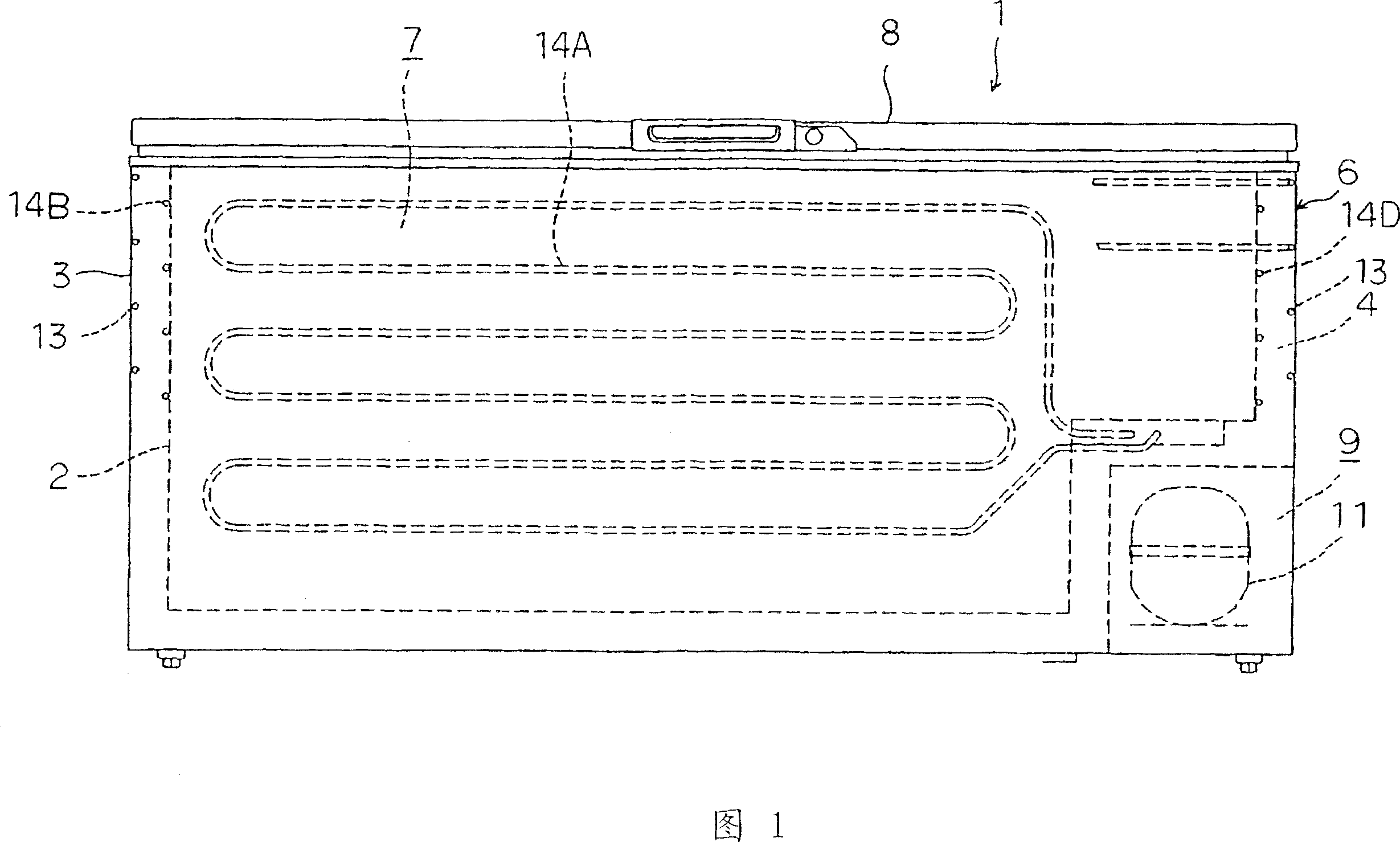
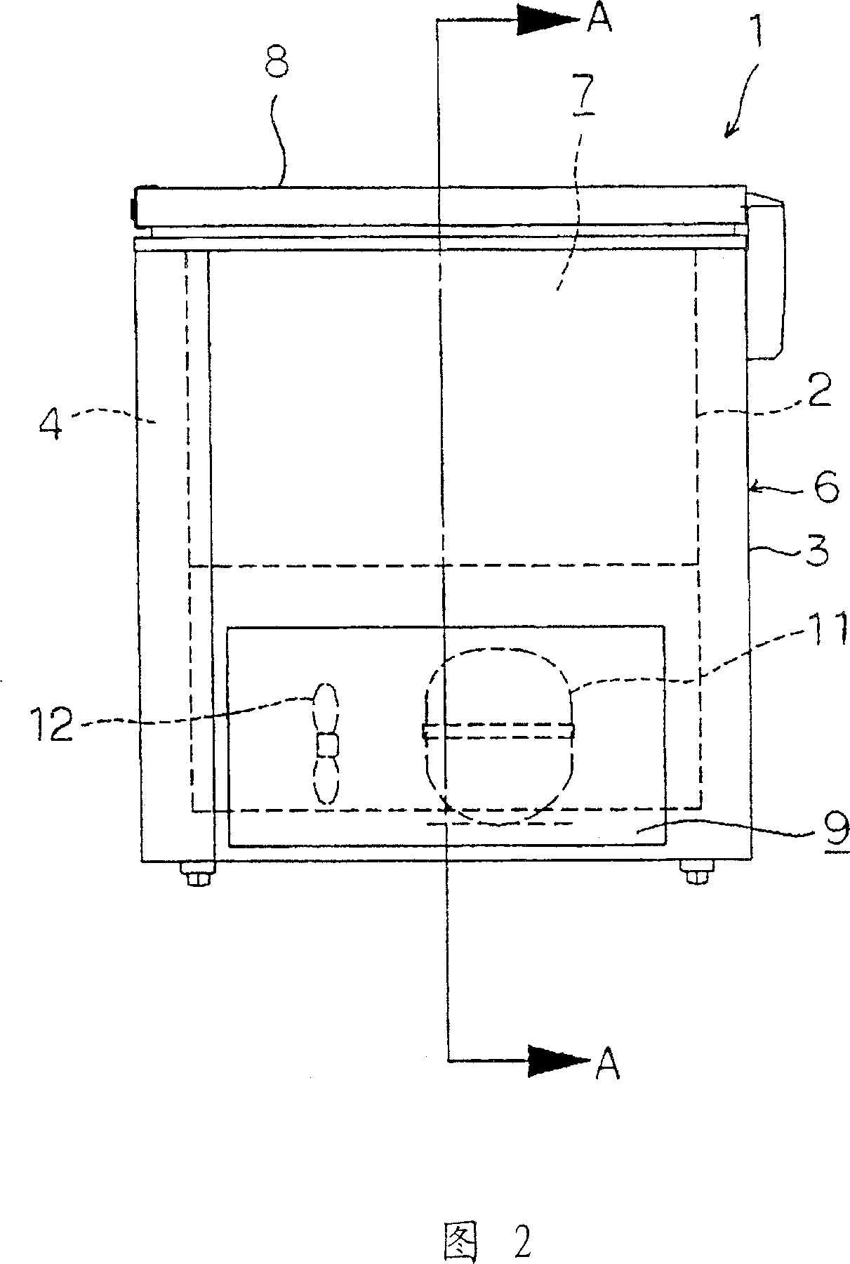
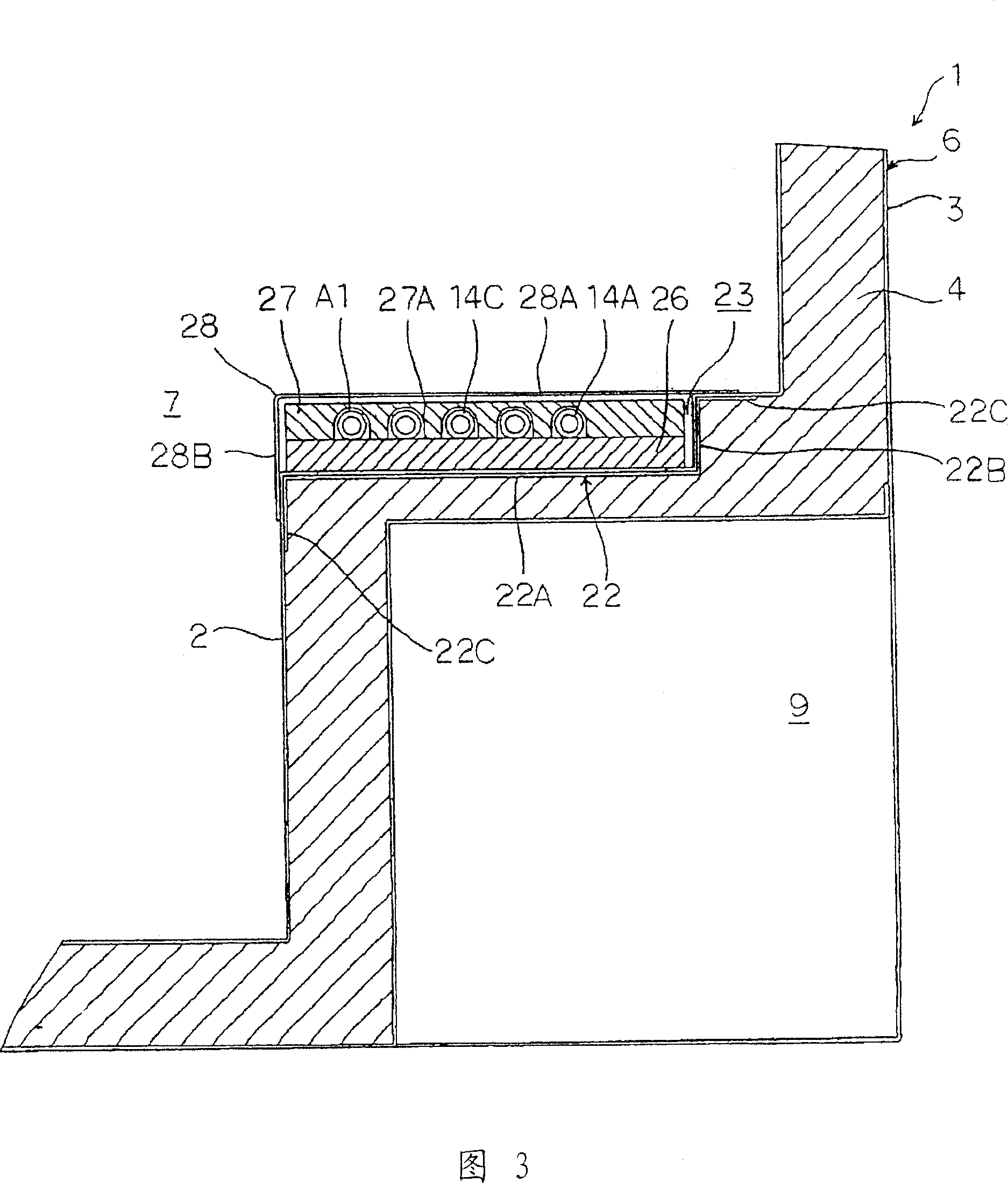
[0028] 1 is a front view of a freezer 1 as an embodiment of the refrigeration storage of the present invention; FIG. 2 is a side view of the freezer 1; FIG. 3 is a cross-sectional view along line A-A of FIG. The freezer 1 of the embodiment is a so-called freezer-type freezer with an upper opening, and includes a heat-insulating box 6 consisting of an aluminum inner box 2 with an upper opening and a steel plate outer casing with an upper opening. The box 3 is composed of on-site foaming to prevent filling between the two boxes 2, 3 with a heat insulating material 4 (hereinafter referred to as a foamed heat insulating material) and the like; the above-mentioned heat insulating door 8 is closed and formed freely The upper surface of the storage room 7 in the inner box 2 is opened.

[0029] An equipment room 9 is formed on the outside of one side (toward the right side) of the heat insulating box 6, and a compressor 11 and a blower 12 constituting a refrigerant circuit of a refrig...

Embodiment 2

[0048] Fig. 5 shows a second embodiment of the present invention. At this time, a plurality of through holes (communication portions) 31 . . . are formed on the bottom surface 22A of the partition plate 22 . In addition, the cooling pipes 14A to 14D, the pipes C1 , A1 introduced into the notch 21 have the welding position W . The cover 32 has a tubular shape, the package is bent along the peripheral surface of each tube, and a slit 32A is formed on the upper surface across the longitudinal direction. Thereby, the cover 32 can observe the welding position W... by opening the notch 32A.

[0049] With such a structure, after the above-mentioned first air leak test is performed, the heat-insulating box adhesion prevention sheet 33 is arranged on the upper surface of the notch 21 (the position formed between the inspection plate 28 and the cooling pipe 14A, etc.), so that The heat insulating foam material 4 is not bonded to the jig. In this state, the inner box 2 is put into the ...


PUM


Abstract

This invnetion discloses a cooling storage cabinet effectively eliminating problems occurring at a welded part of a cooling pipe. A refrigerating chamber 1 comprises an insulation casing 6 formed by foaming and filling a foam heat insulating material 4 between an inner box 2 and an outer box 3 having the cooling pipe 14 fixed on the outer surface. The welded place of the cooling pipe 14 is arranged outside the foam heat insulating material 4. The plurality of cooling pipes 14A, 14C is fixed on the inner box 2 and respectively connected with each other at the welded place. The welded part of the cooling pipes 14 is arranged inside the inner box 2 and covered by a detection plate 28.

Description

technical field [0001] The present invention relates to a refrigerated storage which is composed of a heat-insulating box formed by foam-filling a heat-insulating material between an inner box and an outer box, and a cooling pipe is installed on the outside of the inner box. Background technique [0002] Conventionally, this kind of refrigerating storage, such as a freezer having a so-called tube plate type (Chikobuonshit type) refrigerator with an upper opening, has a plurality of refrigerant circuits attached to the outside of an inner box (for example, made of aluminum). Cooling pipes (made of copper or aluminum) are welded and connected to each other and then put into the outer box. In the state of being arranged in the specified foaming fixture, heat insulating materials such as polyurethane are filled between the two boxes. And constitute a heat insulation box (for example, refer patent document 1). [0003] In such a refrigerated storage room, if the welding position...

Claims


Application Information

Patent Timeline
Patent Type & Authority Patents(China)
IPC IPC(8): F25D23/00F25D19/00F25D11/00
Inventor 中田胜美桑原亨贵
Owner SANYO ELECTRIC CO LTD
Why Eureka
Try Eureka