Shadowless lamp

A technology of shadowless lamp and reflector, applied in the field of medical lamps, can solve the problems of difficulty in uniform incidence of light, difficulty in designing lens steps, and difficulty in manufacturing shadowless lamps, etc., and achieves the effect of easy design, easy design and manufacture

Inactive Publication Date: 2002-06-12
YAMADA IRYO SHOMEI
View PDF0 Cites 12 Cited by
  • Summary
  • Abstract
  • Description
  • Claims
  • Application Information

AI Technical Summary

Problems solved by technology

However, in order to make the light emitted by the bulb 112 incident on the wide surface of the outer lens 114, it is necessary to expand the light beam by the condenser lens 113, but it is difficult to uniformly incident the light beam expanded in this way on the outer lens 114. Therefore, it is difficult to design the outer lens in order to obtain uniform light distribution in the radial and circumferential directions of the shadowless lamp.
And because the incident angles of the light rays entering the outer lens 114 from the condenser lens 113 are different, the lens steps (step) provided on the outer lens 114 for making the incident light refraction inevitably have complex shapes in three-dimensional directions, so It is difficult to design the lens step. At the same time, it is also difficult to make the outer lens 114 by resin molding method, and it is difficult to manufacture a shadowless lamp that meets the design.

Method used


Image

  • Shadowless lamp
  • Shadowless lamp
  • Shadowless lamp

Examples


Embodiment Construction

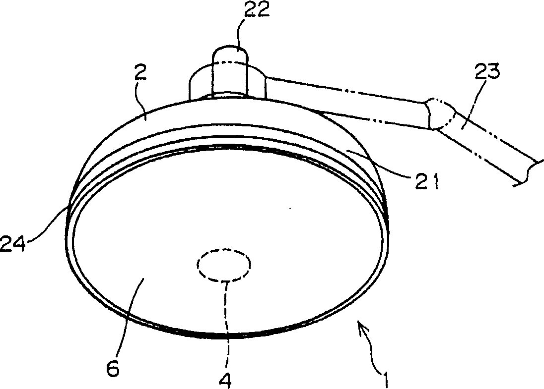
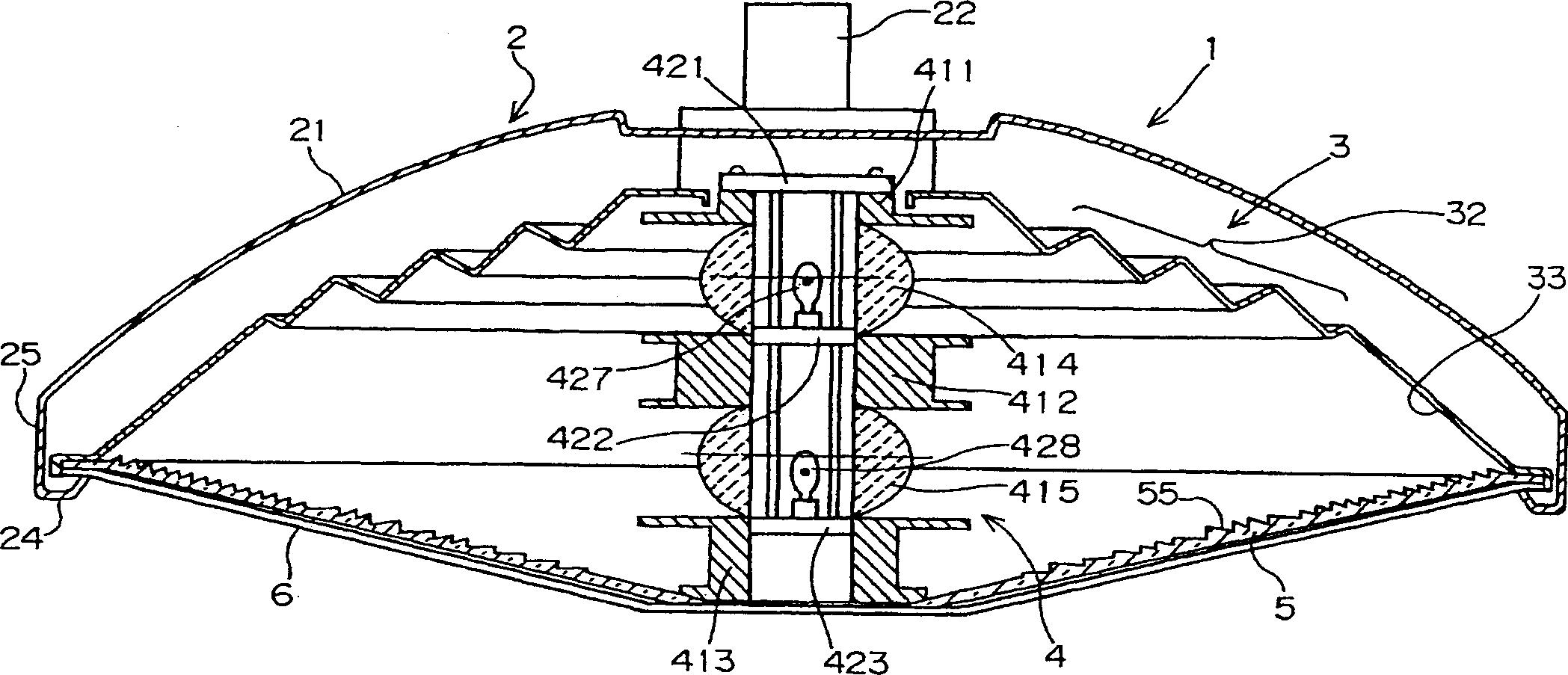
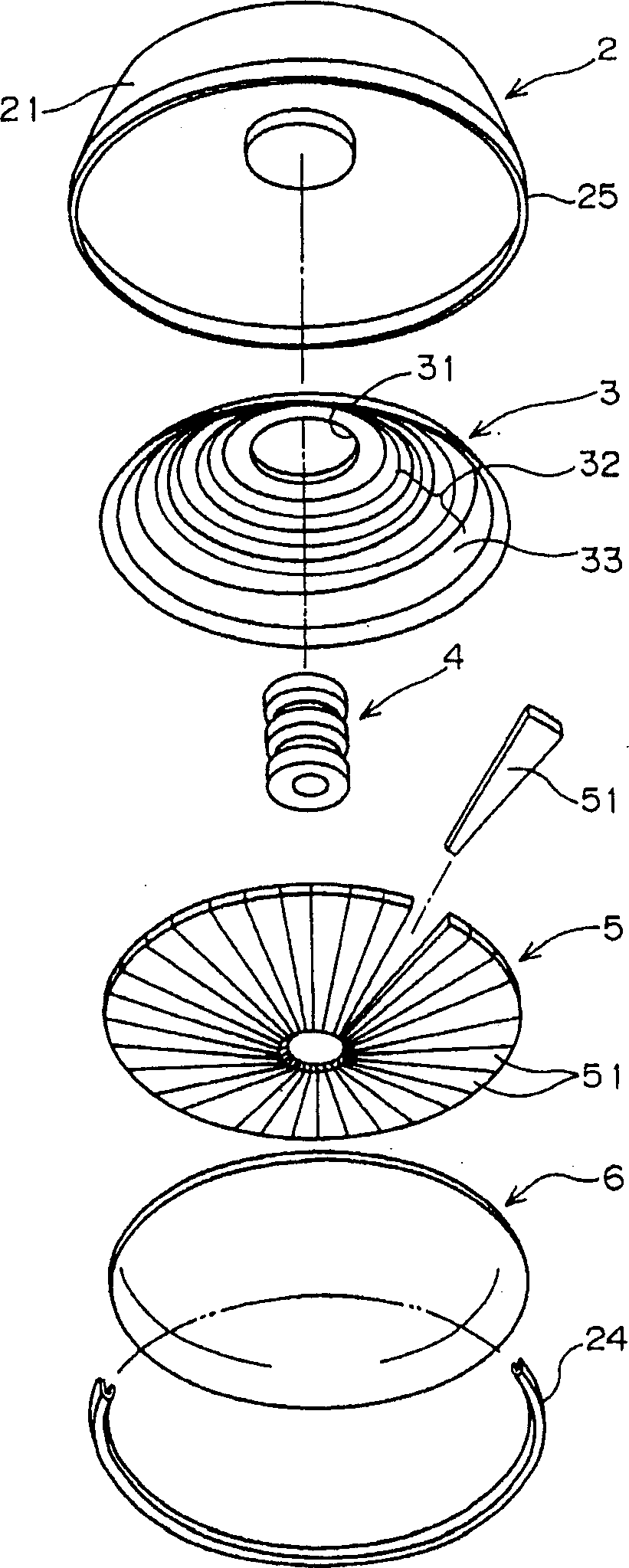
[0024] Embodiments of the present invention will be described below with reference to the drawings. figure 1 It is the appearance diagram of the shadowless lamp of the present invention. figure 2 is a cross-sectional view of its center. image 3 It is an exploded perspective view showing the general structure of each part. In these figures, the cavity 2 of the shadowless lamp 1 has a round umbrella-shaped lamp cavity 21, and an upright cylindrical bolt 22 is arranged at the center of the upper surface of the lamp cavity 21, and the cavity 2 of the shadowless lamp 1 passes through the cylinder. like bolt 22 supported on the figure 1 The support arm 23 shown in the lock line in the figure is electrically connected to the external power supply through the cylindrical bolt 22 inside through the power line outside the figure passing through the bolt to form a structure that can light the bulb. The inside of the lamp cavity 21 is equipped with a reflector 3 which is also in th...


PUM


Abstract

The present invention provides a shadowless light having a light source composed of a small number of electric bulbs, while facilitating the design and manufacture of a lens for achieving a required light distribution characteristic. The shadowless light includes electric bulbs 427 and 428 as light sources; condenser lenses 414 and 415 for causing light beams emitted from the bulbs to be emitted as parallel beams in the circumferential direction; a reflector 3 by which the beams emitted from the condenser lenses are reflected in approximately the same direction at different radial positions with respect to the bulbs serving as centers; and an outer lens 5 refracting the beams reflected from the reflector 3 to achieve the required light distribution characteristic. The beams emitted from the bulbs and the condenser lenses are reflected by the reflector in the form of parallel beams and are made to impinge on the outer lens, where the beams are refracted. The lens step of the outer lens for achieving the required light distribution characteristic therefore, should be designed to refract parallel or approximately parallel beams to achieve the desired light distribution characteristic; the designing of the lens step is facilitated and the shadowless light with the desired light distribution characteristic can be easily designed and manufactured.

Description

technical field [0001] The invention relates to a medical lamp, in particular to a shadowless lamp arranged in an operating room and used for illuminating an operating table. Background technique [0002] As we all know, the shadowless lamp is a lamp used to uniformly illuminate the affected part so that the affected part of the patient on the operating table does not produce the shadow of the doctor or his assistant. The existing general shadowless lamps such as Figure 13 As shown in the external view of (a), a plurality of light bulbs 102 are arranged on the surface of the lamp main body 101, and the light emitted by each light bulb 102 illuminates the affected part from different angles. The shadow produced by one light bulb is replaced by the light from other light bulbs. The light is offset to form a structure that prevents the shadow of the operator. Also, other existing shadowless lamps such as Figure 13 As shown in the sectional view of (b), the scheme is that a l...

Claims


Application Information

Patent Timeline
IPC IPC(8): F21S2/00A61B19/00F21V5/00F21V5/04F21V7/00F21V7/04F21V13/00F21V13/04F21V13/12F21W131/205F21Y101/00G02B27/00
CPCF21W2131/205F21V7/0066F21V7/10G02B27/30
Inventor 松下真人
Owner YAMADA IRYO SHOMEI
Why Eureka
Try Eureka