Method for processing photographic material

A technology for photographic materials and processing liquids, which is used in photosensitive materials, circulating liquid processing, liquid spray liquid processing, etc., and can solve problems such as one-way valve leakage, application of processing liquid, and inability to transport liquids.

Inactive Publication Date: 2002-07-24
EASTMAN KODAK CO
View PDF1 Cites 0 Cited by
  • Summary
  • Abstract
  • Description
  • Claims
  • Application Information

AI Technical Summary

Problems solved by technology

One-way valves can become clogged and fluid cannot be delivered
Check valves c

Method used


Image

  • Method for processing photographic material
  • Method for processing photographic material
  • Method for processing photographic material

Examples


Embodiment Construction

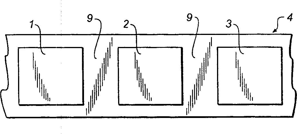
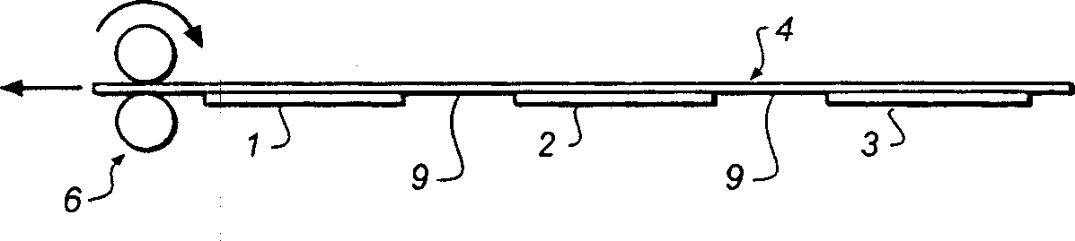
[0016] Figure 1A A top view showing individual treatment fluid sachets arranged one after the other. Figure 1B Side view showing individual treatment fluid sachets arranged one after the other.

[0017] A movable belt 4 is placed over the photographic material to be processed. This material is not shown in the figure. A number of sachets, ie seals 1, 2, 3 are placed on the movable belt 4 in sequence in the processing cycle. The pouch can be made of any suitable material that is inert to the treatment fluid. For example, the pouch may be made of thin lead foil with a plastic coating, or of any suitable flexible plastic, such as polyethylene or polypropylene. It should be understood that these are examples only.

[0018] The solution in the sachet is pre-weighed to the correct volume amount required for processing. In Fig. 1, sachet 1 contains developer solution, sachet 2 contains bleach solution, and sachet 3 contains fixer solution. It should be understood that there a...


PUM


Abstract

A method of delivering processing solution to a processing device wherein the processing solutions are provided within sealed members fixedly arranged on a movable web. The web moves relative to the processing area and the sealed members are ruptured when the processing solution within is required.

Description

technical field [0001] This invention relates to methods and apparatus for processing photographic material. In particular, the invention relates to a method of charging a treatment liquid into a treatment machine. Background technique [0002] Traditional photographic material processing requires the use of large tanks that are individually filled with processing fluids. Each tank contains a processing solution such as developer, bleach, fixer or cleaning solution. The photographic material passes sequentially through the slots. The solution is easily carried from one tank to another, contaminating the solution. Traditional processing methods also have some other disadvantages. The temperature at which it can be used is limited, so processing is slow. The composition of the solution must remain stable over time in the treatment tank. Solution replenishment is also difficult to control. Since there are many processing tanks, the processing equipment is very large. ...

Claims


Application Information

Patent Timeline
IPC IPC(8): G03D3/06G03D5/02G03D5/04G03D13/02
CPCG03D5/02
Inventor P·J·特威斯特N·R·怀尔德曼
Owner EASTMAN KODAK CO
Why Eureka
Try Eureka