Reflector-movable front-lighting lamp for automobile

A technology for reflectors and headlights, applied in the direction of headlights, vehicle lighting systems, lighting devices, etc., can solve the problems of damaging the rotation performance of the headlight adjustment screw 4, difficult operation of headlight adjustment, and inability to properly adjust, etc., to achieve Expand the range of relative rotation, ensure smooth rotation, and avoid the effect of mutual influence

Inactive Publication Date: 2002-08-07
KOITO MFG CO LTD
View PDF1 Cites 15 Cited by
  • Summary
  • Abstract
  • Description
  • Claims
  • Application Information

AI Technical Summary

Problems solved by technology

[0007] However, there is such a problem: if the clamping force of the plug-in fixing device 8 to the headlight adjustment screw 4 is increased, the rotation performance of the headlight adjustment screw 4 will be impaired, and it will be difficult to adjust the headlight.
[0009] However, with the above-mentioned prior art (Japanese Patent Application No. 2000-165437), since the weight on the side of the reflector 2 is borne by the slide rail 8, although the weight load on the side of the reflector 2 does not act on the headlight adjustment screw as a bending moment. 4, but since the inertial weight on the side of the reflector acts on the coupling protrusion 6 biased on the side of the nut part body 5 screwed on the headlight adjustment screw 4, the nut part will generate torque, and it is difficult to reliably control the position of the reflector. shock
and, if Figure 20 If this torque is applied repeatedly to the nut assembly, as indicated by the blank arrow, the nut will turn freely relative to the headlight adjustment screw and may not adjust properly
[0010] In addition, the nut part is viewed as a T-shape or an L-shape, which causes the problem of increasing the size of the lamp body.

Method used


Image

  • Reflector-movable front-lighting lamp for automobile
  • Reflector-movable front-lighting lamp for automobile
  • Reflector-movable front-lighting lamp for automobile

Examples


Embodiment Construction

[0076] Next, embodiments of the present invention will be described based on examples.

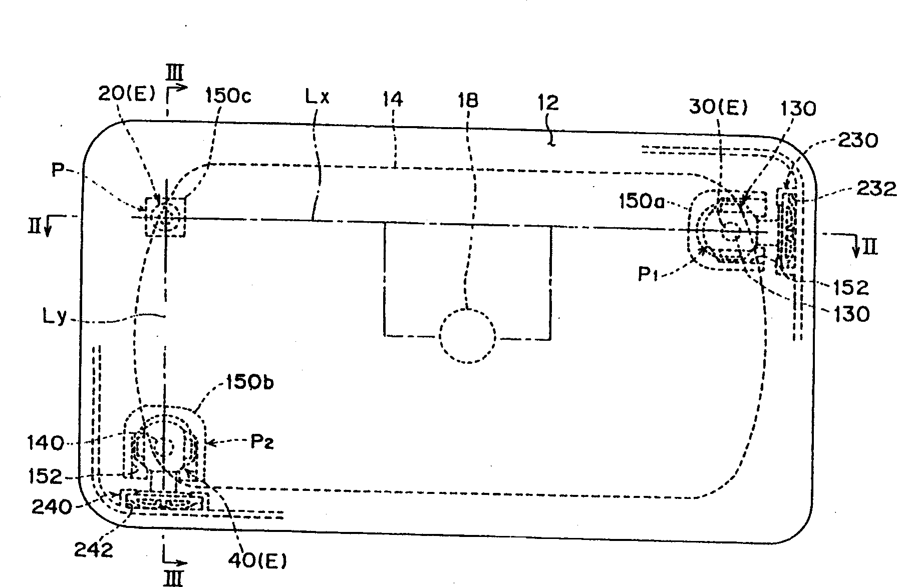
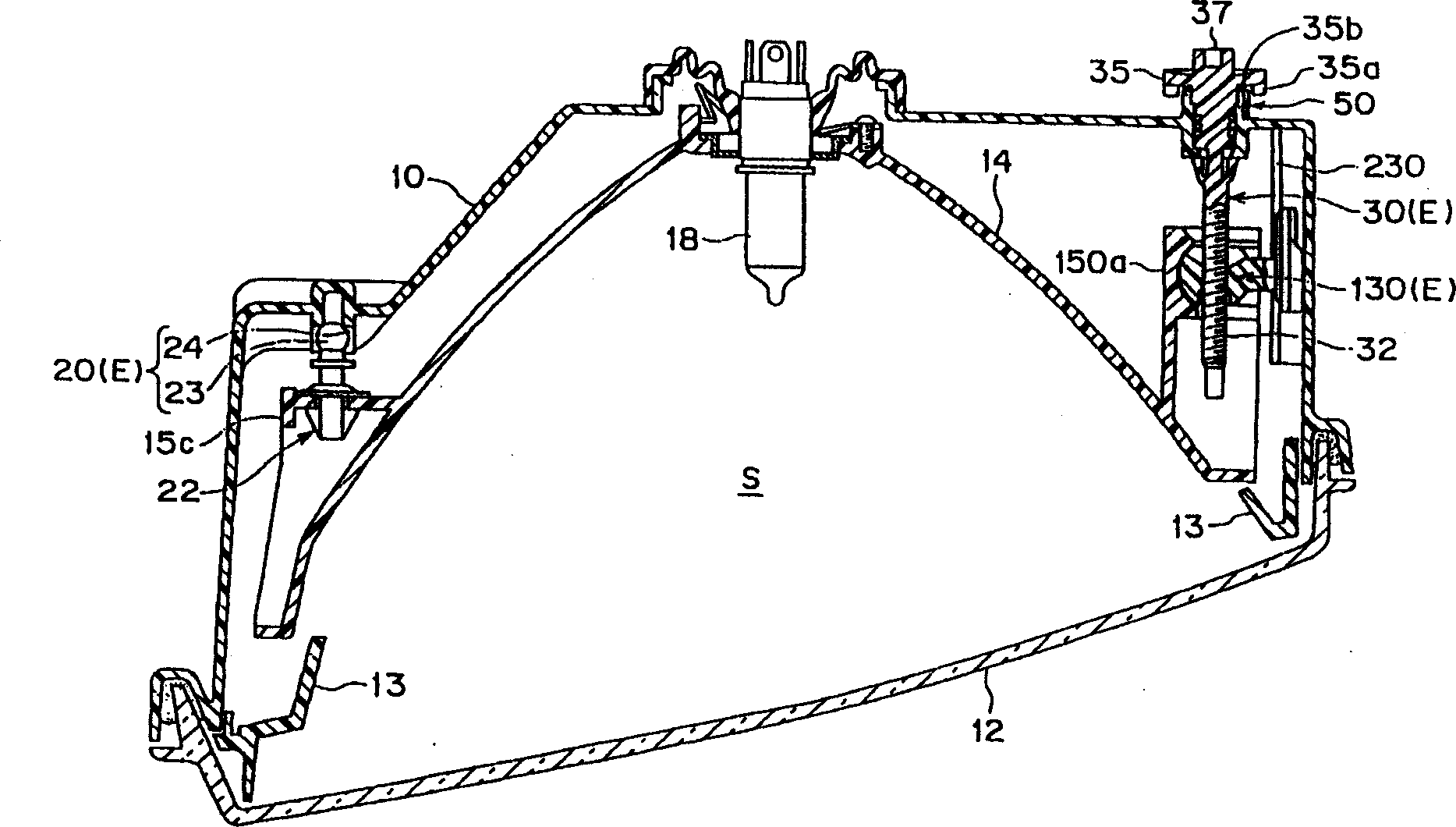
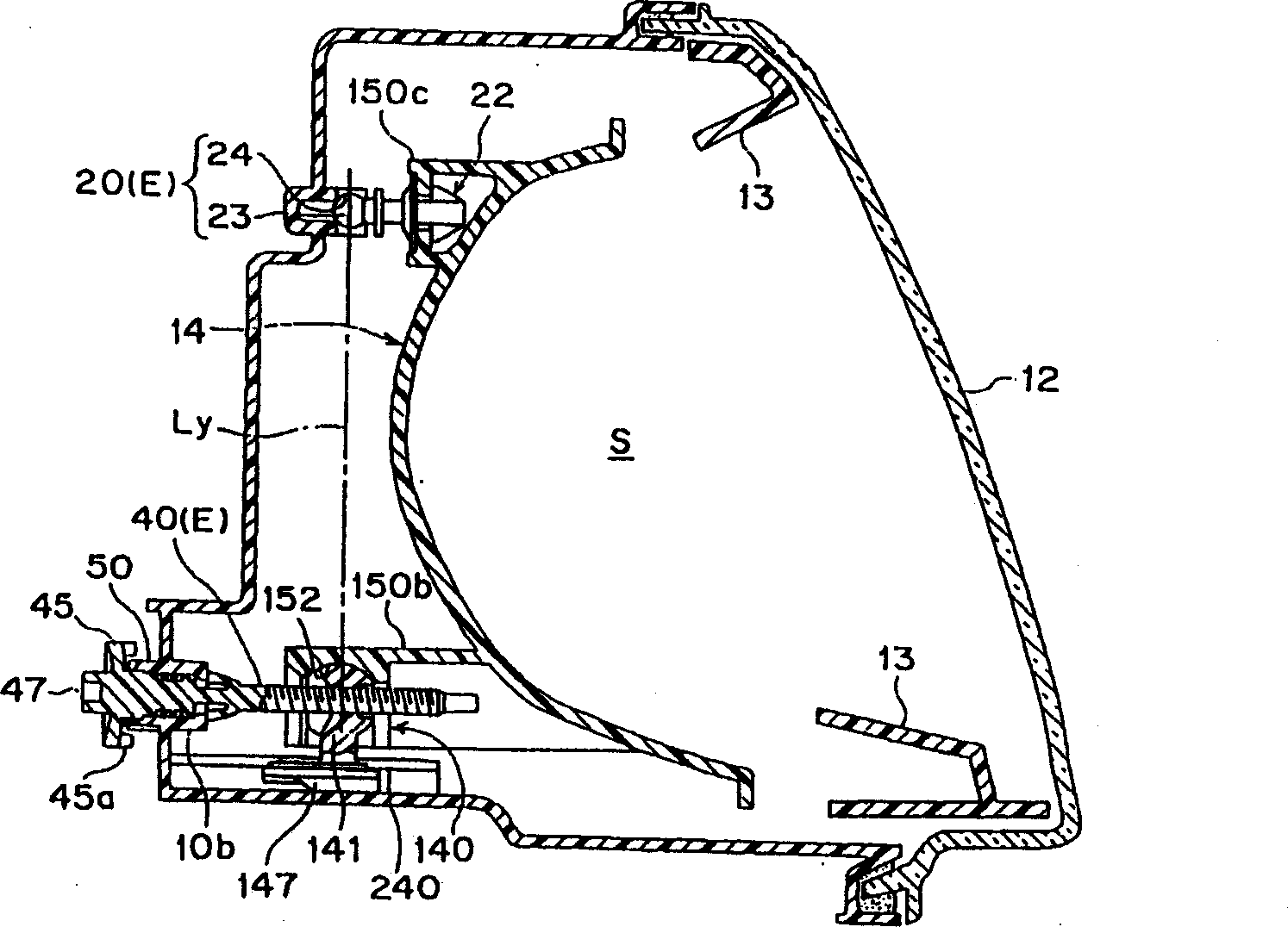
[0077] Figure 1 to Figure 17 It is the first embodiment of the present invention. figure 1 It is a front view of the first embodiment of the present invention - a movable reflector type automobile headlamp. figure 2 It is a horizontal sectional view of the headlamp (along figure 1 Sectional view of line II-II shown). image 3 It is a longitudinal sectional view of the headlamp (along figure 1 Sectional view of line III-III shown). Figure 4 It is an exploded oblique view of the lamp body, reflector and adjustment device. Figure 5 (a) is an enlarged perspective view of the cylindrical portion, and (b) is an enlarged longitudinal sectional view of the cylindrical portion, which is a cylindrical portion constituting the rotation support portion of the adjusting screw. Figure 6 is the adjusting screw, (a) is the enlarged oblique view of the adjusting screw, (b) is the enlarged sid...


PUM


Abstract

The invention provides a compact head lamp for reflector movable type automobile capable of preventing vibrations of a reflector and smoothly rotating an aiming screw. In this head lamp, a nut sliding guide 230 equipped to a bracket 150a in a reflector 14 side, screwed with a screw 30, and guides a nut member 130 moving forward / backward in relation to rotations of the screw 30 is provided on a lamp body. A stress releasing means having a ball joint structure is provided between the nut member 130 composing a aiming point P1 and the bracket 150a. The sliding guide 230 carries the weight of the reflector 14, guarantees sliding of the nut member 30. Torsional moment is not generated on the nut member 30, so that vibrations of the reflector 14 can be suppressed, and smooth rotations of the screw can be ensured.

Description

technical field [0001] The invention relates to a headlamp for automobiles with a movable reflector. The reflector equipped with a light source is supported tiltably and movable relative to the lamp body through a headlamp adjustment device. In particular, the present invention relates to such a movable reflector type automotive headlight, which is structured as a headlight adjustment point component-nut component screwed to the headlight adjustment screw of the headlight adjustment device component component , supported by a nut sliding guide rod formed on the lamp body. Background technique [0002] Such as Figure 19 As shown, the existing reflector movable type automobile headlamp is supported by the headlight adjustment device, and in the headlight adjustment device, the synthetic resin reflector 2 integrally installed with the light source is placed on the synthetic resin lamp body 1. On the front side, there is a ball joint as a fulcrum for tilting movement, and two ...

Claims


Application Information

Patent Timeline
Patent Type & Authority Applications(China)
IPC IPC(8): B60Q1/06B60Q1/068F21S8/10F21V14/04F21W101/10F21Y101/00
CPCF21S48/25B60Q1/0683B60Q2200/32F21S43/50
Inventor 白井克忠
Owner KOITO MFG CO LTD
Why Eureka
Try Eureka