Power component, driving regulator and networking method for regulating element and power component

A technology of power components and regulating units, applied in the control of motor speed or torque, electrical components, motor generator control, etc., can solve communication bottlenecks, wrong settings, increase costs, etc., and achieve the effect of flexible quantity

Inactive Publication Date: 2002-09-11
SIEMENS AG
View PDF0 Cites 2 Cited by
  • Summary
  • Abstract
  • Description
  • Claims
  • Application Information

AI Technical Summary

Problems solved by technology

This means additional fees, which increase the cost of
There is also the possibility of wrong settings
[0005] For cost reasons, the pulse interface is a communication bottleneck in known systems

Method used


Image

  • Power component, driving regulator and networking method for regulating element and power component
  • Power component, driving regulator and networking method for regulating element and power component
  • Power component, driving regulator and networking method for regulating element and power component

Examples


Embodiment Construction

[0046] Hereinafter, embodiments of the present invention will be described in detail with reference to the drawings.

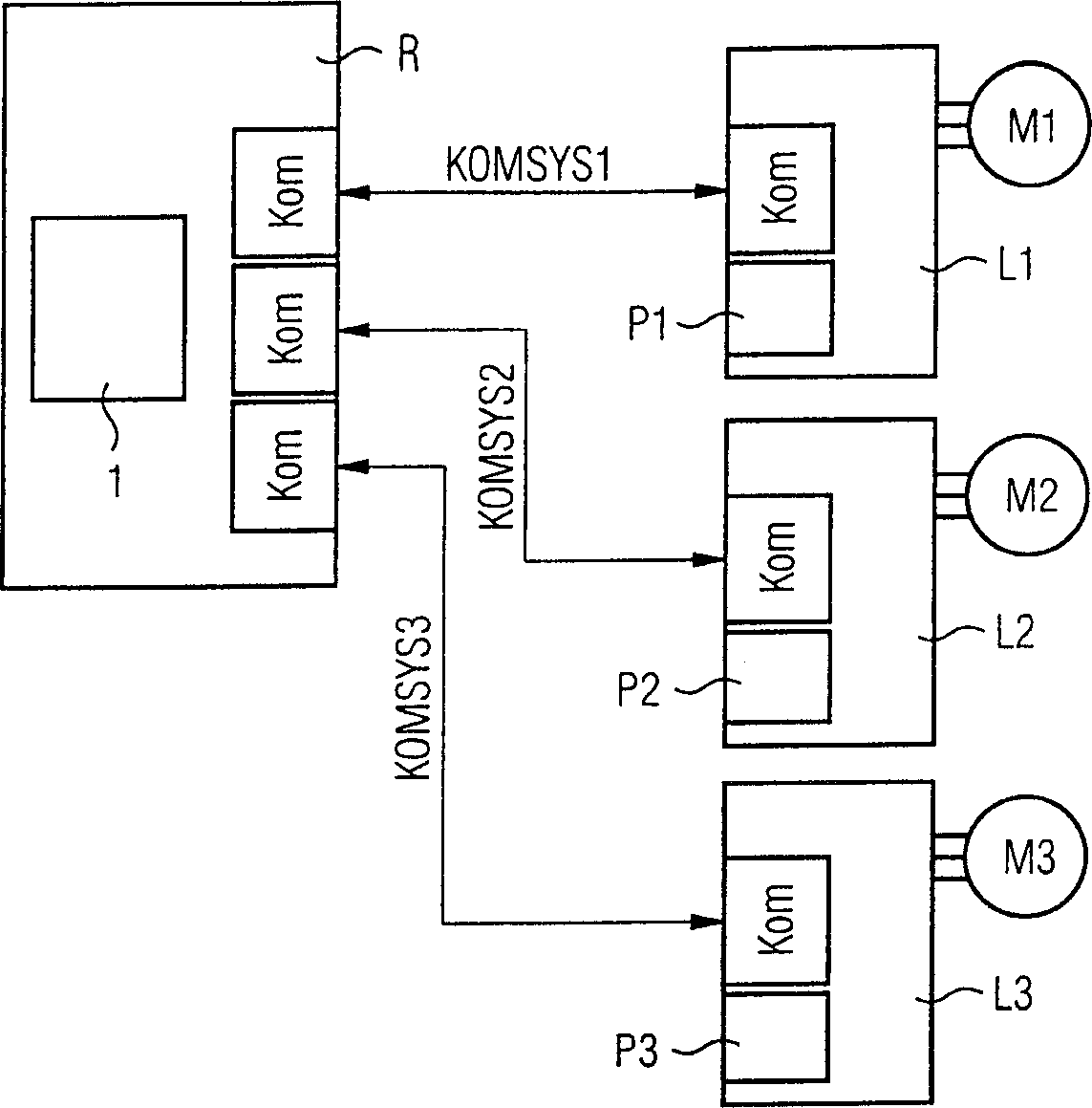
[0047] Such as figure 1 As shown, the drive controller for 3 motors M1 to M3 has a communication network, which includes 3 different communication systems KOMSYS1, KOMSYS2 and KOMSYS3, via which the power components L1 to L3 corresponding to the motors are connected to the superordinate The regulating unit R communicates. In the configuration shown, for example, three interconnected drives of industrial processing machines, such as machine tools or robots, can be present.

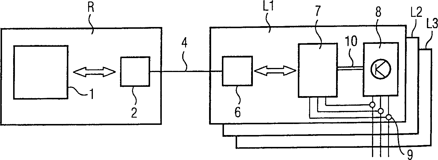
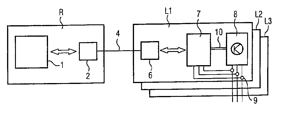
[0048] According to the invention, by using the high-power synchronous transmission systems KOMSYS1 to KOMSYS3, it is possible to partly transfer computing power from the regulation unit R to the power components L1 to L3. The regulating unit comprises a regulating processor 1 , the corresponding power components L1 to L3 are additionally assigned to microprocessors or microcontrollers P1...


PUM


Abstract

Intelligent distribution of the transmission on a regulating unit R and one or more intelligent power components L1 to L3 and interconnection of these components with standardized serial interfaces 2, 4, 6 that can be used under high power conditions, above The scheme can realize the identification and judgment of different power components and their performance data. In addition, components can be modified independently without corresponding effects on other components.

Description

technical field [0001] The invention relates to a power unit for controlling an electric drive, a drive regulator based on the power unit and a networking method between one or more of the power units. Background technique [0002] Previously known drive controllers exchange information between an intelligent controller (for example a drive processor) and passive power components via a so-called pulse interface. This pulse interface has not been standardized so far and cannot be freely replaced even in the manufacturer's drive development. [0003] On the one hand, the task of the controller (besides its own regulation algorithm and drive function) is to supply the transistors of the power components with optimal control pulses. For this purpose, on the side of the known regulator there is a control module located at the output of the current regulator, which converts the setpoint voltage value, which is usually present as voltage value and voltage ...

Claims


Application Information

Patent Timeline
Patent Type & Authority Applications(China)
IPC IPC(8): H02P5/00
CPCH02P5/00H04J3/0664H04L7/08H02P6/04H02P8/40
Inventor 格哈德·海涅曼乔基姆·姆希亚历山大·瓦根菲尔
Owner SIEMENS AG
Why Eureka
Try Eureka