System for communicating operational data between electric toothbrush and separate control unit

A control device, the technology of electric toothbrush, used in dentistry, brushes, prosthetics, etc.

Inactive Publication Date: 2002-09-25
KONINKLIJKE PHILIPS ELECTRONICS NV
View PDF1 Cites 7 Cited by
  • Summary
  • Abstract
  • Description
  • Claims
  • Application Information

AI Technical Summary

Problems solved by technology

Moreover, other information about the operating condition of the toothbrush, such as the st

Method used


Image

  • System for communicating operational data between electric toothbrush and separate control unit
  • System for communicating operational data between electric toothbrush and separate control unit
  • System for communicating operational data between electric toothbrush and separate control unit

Examples


Embodiment Construction

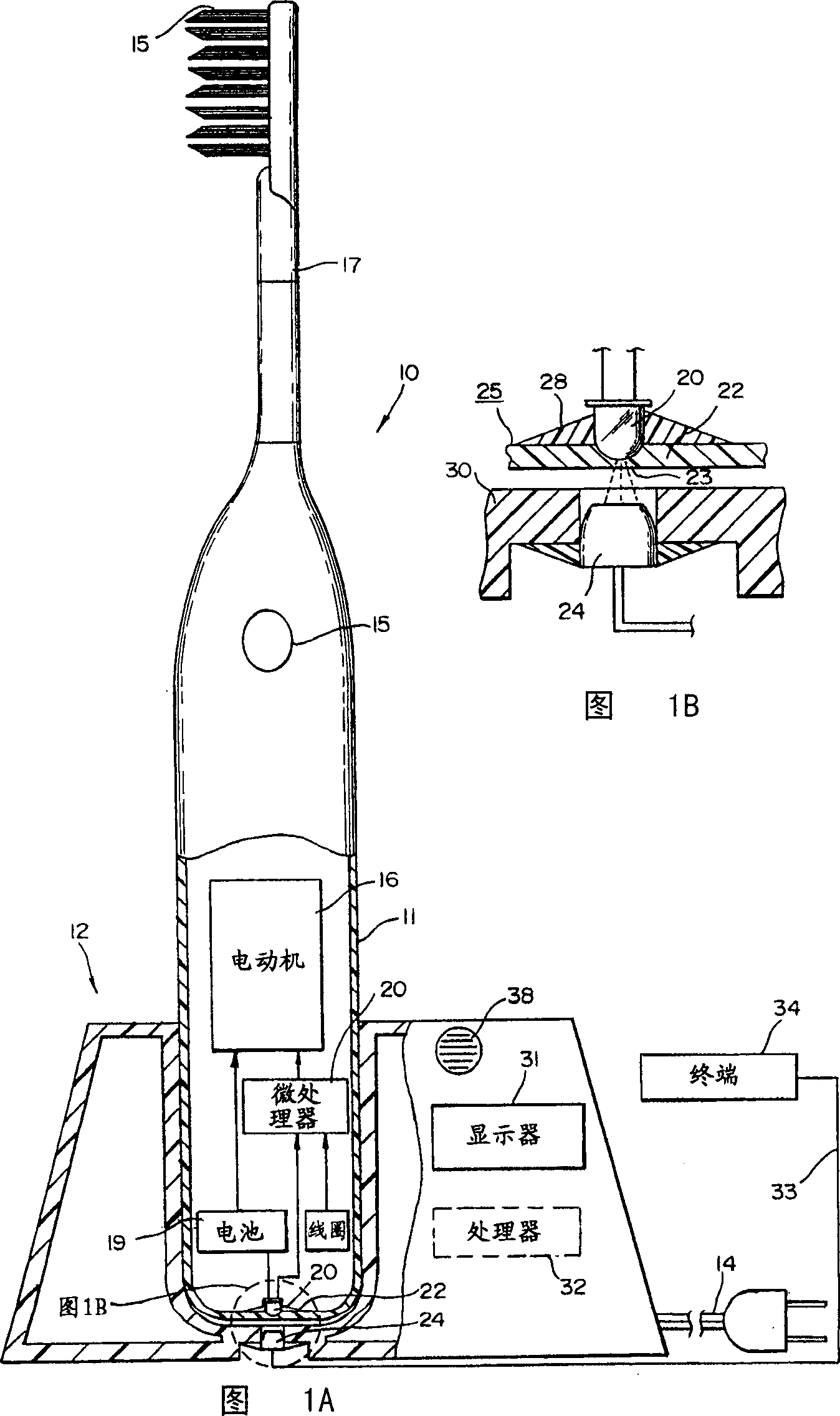
[0011] 1A and 1B show a particular embodiment of the present invention, in particular a battery operated electric toothbrush 10 which includes a handle portion 11 which in turn houses a control unit 12 . As used herein, the terms control device and control base refer to both base devices without battery charging capabilities and base devices with battery charging capabilities. Toothbrush 10 may have a separate charging device that holds the ability to charge the battery. The control device may be separate from the charging device or the functionality of the control device may be incorporated into the charging device. The control device 12 is connected to the wall by means of a power cord and a plug 14 . In the illustrated embodiment, the toothbrush 10 includes a brush head 15 mounted on a lever arm 17 . The lever arm itself is in turn vibrated about the pivot by means of an electromagnetic motor 16 contained in the handle 11 . The electric motor 16 itself is driven by a bat...


PUM


Abstract

A system for transmitting data between a battery-operated electric toothbrush and a separate control unit contains a microprocessor in the toothbrush that collects and stores data about the operation of the selected toothbrush. Data is transmitted from the toothbrush to the control unit by means of an infrared link. The transmitted data are processed in the control unit and displayed there, or are transmitted to a separate device for display and/or analysis.

Description

technical field [0001] The present invention relates generally to battery-operated electric toothbrushes, and more particularly to toothbrushes capable of providing information about the use of the toothbrush to a separate control device which itself can display or analyze the information or transmit the information to another device . Background of the invention [0002] Both manual and powered toothbrushes operate in various ways to produce a cleaning action on the user's teeth. A few toothbrushes attempt to provide specific information about the operation of the toothbrush to the user during use. In many cases, this information is a reading of expected or actual cleaning times. In other cases, information is provided about the pressure exerted by the user on the toothbrush against the teeth, whereas the pressure is determined in a different manner and subsequently displayed or otherwise transmitted to the user. However, it is generally difficu...

Claims


Application Information

Patent Timeline
IPC IPC(8): A46B17/00A46B15/00A61C17/22
CPCA61C17/22A61C17/221A61C17/224A61C2204/002
Inventor W·G·伦德尔D·巴耶
Owner KONINKLIJKE PHILIPS ELECTRONICS NV
Why Eureka
Try Eureka