Brightness control method for optical image detector

A technology of optical image and brightness control, applied in optics, exposure control, nonlinear optics, etc., can solve problems such as residual images

Inactive Publication Date: 2002-11-06
ATLAB INC
View PDF0 Cites 14 Cited by
  • Summary
  • Abstract
  • Description
  • Claims
  • Application Information

AI Technical Summary

Problems solved by technology

Therefore, when the exposure time of the electric shutter 13 is very long in the known optical image detector, there will be a problem of residual image.

Method used


Image

  • Brightness control method for optical image detector
  • Brightness control method for optical image detector
  • Brightness control method for optical image detector

Examples


Embodiment Construction

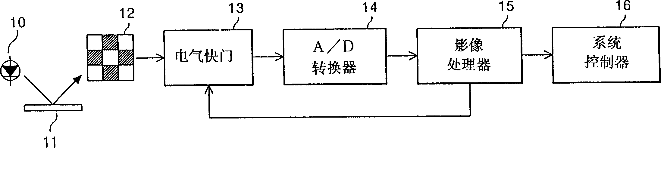
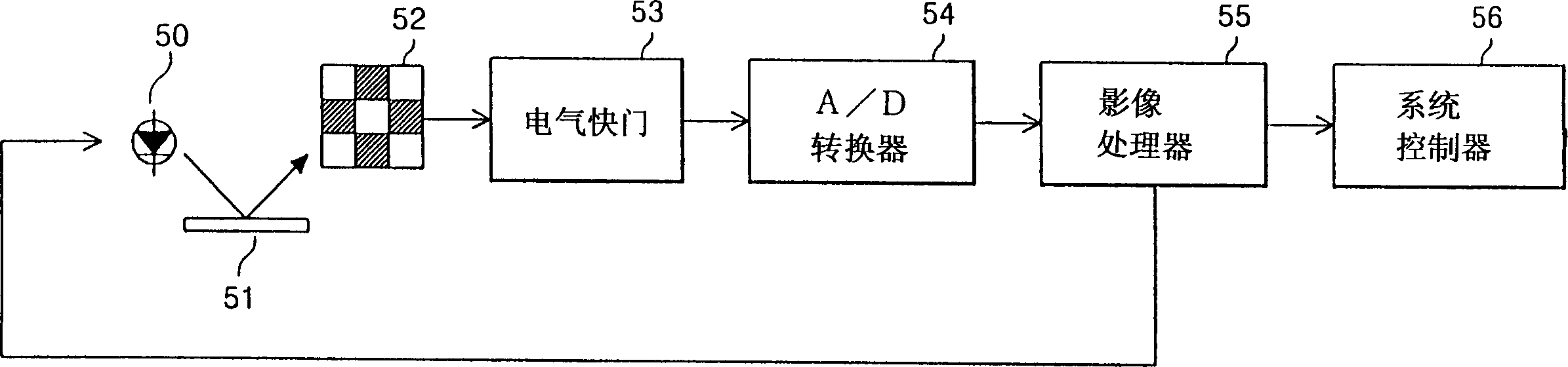
[0042] image 3 It is a block diagram of the brightness control method of the optical image detector of the present invention. The optical image detector includes a light source 50 , an object 51 , an optical image sensor 52 , an electrical shutter 53 , an A / D converter 54 , an image processor 55 , and a system controller 56 .

[0043] The light source 50 has a predetermined brightness. The object 51 reflects incident light from the light source 50 . The optical image sensor 52 detects the reflected light reflected from the object 51 and outputs a photocurrent or a photovoltage proportional to the incident light. The electrical shutter 53 adjusts the exposure time interval of the photocurrent or the photovoltage and captures an optical signal. The A / D converter 54 converts the optical signal captured through the electrical shutter 13 into a digital signal. The image processor 55 controls the digital signal converted by the A / D converter 54 to output an optical image signal...


PUM


Abstract

The invention discloses a brightness control method of an optical image detector, which is used for detecting an incident optical image when the light of a light source reflects an object, and controls the brightness of the light source according to the detected incident optical image. The optical image detector detects the light through an image sensor or an electric shutter, and an image processor or a system controller directly adjusts the brightness of the light source according to the detected incident optical image. According to the brightness control method of the optical image detector of the present invention, the image quality of the object can be improved by removing the image noise and residual image caused by insufficient brightness of the light source, and the consumption of power supply can be reduced by directly adjusting the brightness of the light source.

Description

technical field [0001] The invention relates to a brightness control method of an optical image detector, which detects an incident optical image when light from a light source reflects an object, and controls the brightness of the light source according to the detected incident optical image. Therefore, the brightness control method according to the present invention can improve the quality of the optical image and optimize the consumption of the power supply. Background technique [0002] Generally, optical image detectors are applied in digital cameras, video cameras, solid-state imaging devices, and optical mice. The optical image detector includes a light element with predetermined brightness and detects the optical image of the object through reflected light when the light element illuminates an object. [0003] Such as figure 1 As shown, a known optical image detector for receiving light reflected by an object and detecting an optical image of the object includes a ...

Claims


Application Information

Patent Timeline
Patent Type & Authority Applications(China)
IPC IPC(8): G03B7/00G01J1/42
CPCG01J1/42G03B7/00
Inventor 郑德暎李芳远
Owner ATLAB INC
Why Eureka
Try Eureka