Manual tool changing apparatus

A tool holder and tool holder technology, which is applied in the field of tool changing devices, can solve the problems such as the inability of machining centers to produce

Inactive Publication Date: 2002-11-27
HURCO
View PDF1 Cites 3 Cited by
  • Summary
  • Abstract
  • Description
  • Claims
  • Application Information

AI Technical Summary

Problems solved by technology

Obviously, the process requires considerable downtime because the tool change takes up the machining spindle of the machine and keeps the machining center from being productive

Method used


Image

  • Manual tool changing apparatus
  • Manual tool changing apparatus
  • Manual tool changing apparatus

Examples


Embodiment Construction

[0028] To facilitate an understanding of the principles of the invention, reference will now be made to the embodiments illustrated in the drawings, and specific language will be used to describe the same. It should be understood, however, that no limitation of the scope of the invention is intended. The present invention includes any substitutions and further modifications to the illustrated devices, described methods, and other applications of the principles of the invention that would normally occur to those skilled in the art to which the invention pertains.

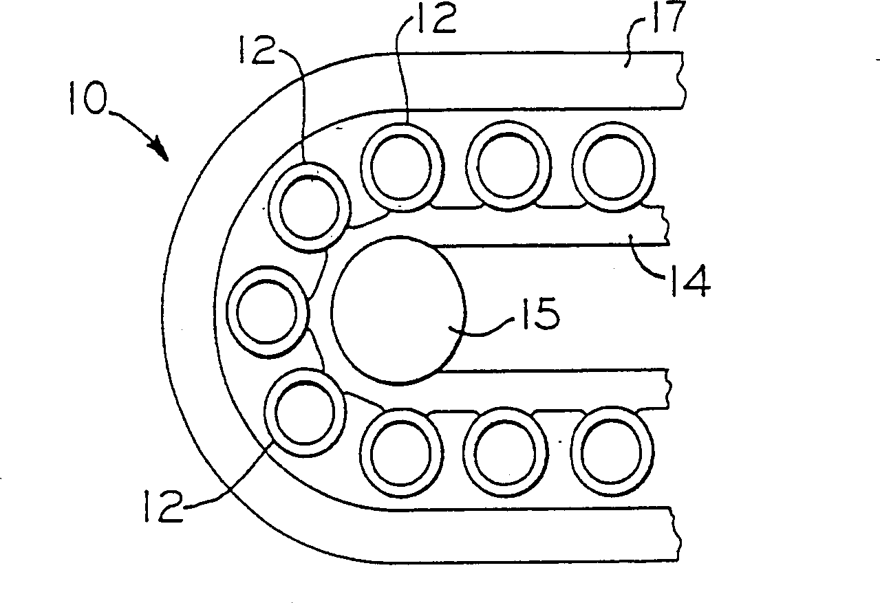
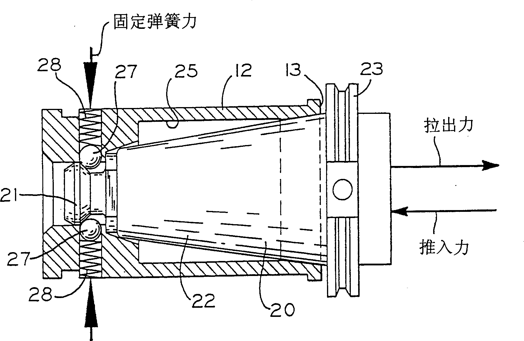
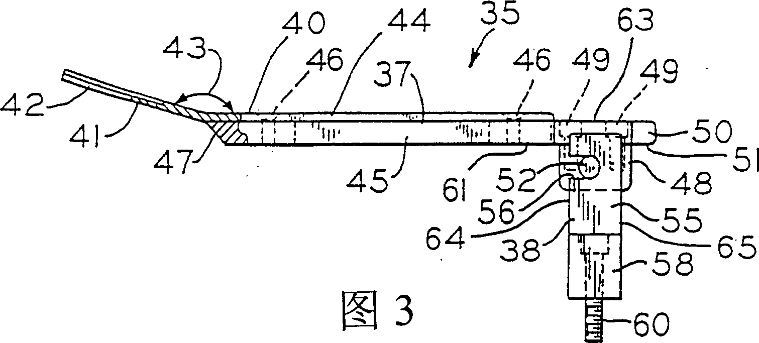
[0029]The invention relates to a tool insertion / removal device particularly suitable for automatic machining centers. More specifically, the apparatus includes a multifunction tool and pivot bracket mounted on the tool bed housing. The multi-function tool is an elongated rod having an extraction member at a first end configured to pry the handle of the tool out of engagement with the tool holder. The other end of t...


PUM


Abstract

A manually operated apparatus for removal and insertion of a tool holder to and from a tool pocket of a magazine includes two components-a multi-function insertion / removal tool, and a pivot bracket. The multi-function tool generally comprises an elongated bar having a tool holder removal element at one end and an insertion element at the opposite end. The removal element can constitute a known pry tool having a fork portion configured to facilitate insertion between the rim of the tool pocket and the underside of the circumferential flange of the tool holder. The insertion element of the multi-function insertion / removal tool comprises a pivot block and a pressure plate. The pivot block includes a pivot pin projecting therefrom that is configured for pivoting engagement within a channel defined in the pivot bracket. The pivot bracket is mounted to the housing of the tool magazine at a manually accessible location relative to the tool pockets with the open end of the channel facing away from the tool pocket. When the pivot pin of the insertion / removal tool is disposed within the channel of the pivot bracket, the pressure plate is situated over a portion of the circumferential flange of the tool holder when the holder is loosely disposed within the tool pocket. The elongated bar of the tool can be used as a lever arm to pivot the tool about the fulcrum point defined by the pivot pin and pivot bracket. As the elongated bar is manipulated, the pressure plate is pivoted downward, bearing against the circumferential flange of the tool holder with sufficient force to overcome the pocket spring force operating against the knob of the tool holder.

Description

technical field [0001] The invention relates to a tool changing device for changing tools mounted in a tapered tool holder. The invention is particularly applicable to automatic machining centers having tool beds for storing tools for sequential machining operations. Background technique [0002] A typical CNC machine tool system includes a machining center with a tool bed and a tool changing mechanism. This mechanism removes a specific tool from the machining spindle and replaces it with a different tool that is removed from the tool bed. With this type of machining center, a wide variety of machining processes can be carried out which require a corresponding number of various machining tools. Thus, a variety of tools are stored on the tool bed or tool rack for ready use. [0003] In the development of modern machining centers, considerable attention has been focused on the tool change mechanism, that is, the device that removes a specific tool from the tool bed and puts...

Claims


Application Information

Patent Timeline
Patent Type & Authority Applications(China)
IPC IPC(8): B23Q3/155B25B27/00B25B33/00
CPCB23Q3/15533B25B27/00B25B33/00Y10T483/1736Y10T483/15Y10T483/1818
Inventor H·帕特尔M·利休
Owner HURCO
Why Eureka
Try Eureka