Automatic nail feeder

A nail feeding and automatic technology, which is applied to nail staple tools, manufacturing tools and other directions, can solve the problems of troublesome operation and high use cost of automatic tools, and achieve the effect of low use cost, improved work efficiency and work quality, and ingenious structure.

Inactive Publication Date: 2003-01-08
甘仲光
View PDF0 Cites 8 Cited by
  • Summary
  • Abstract
  • Description
  • Claims
  • Application Information

AI Technical Summary

Problems solved by technology

[0003] What the present invention aims to solve is the need to use special equipment to install the nails on the special nail belt, the technical problems of high cost of automatic tools and troublesome operation

Method used


Image

  • Automatic nail feeder
  • Automatic nail feeder
  • Automatic nail feeder

Examples


Embodiment 1

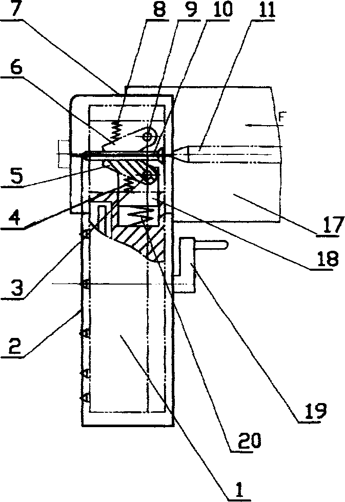
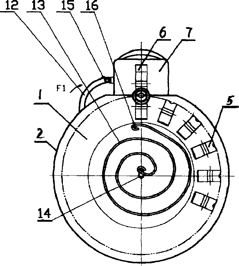
[0014] Embodiment 1: The nail feeder has a nail tray 1, the nail tray 1 is located below the gun head 7, the nail tray 1 is evenly distributed with a claw device, the nail tray 1 is connected with a shell 2, the nail tray 1 center is connected with coil spring 13.

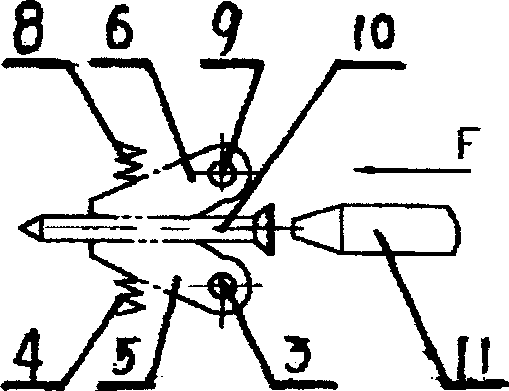
[0015] The gun head 7 is connected with the jaw B6, and one end of the jaw B6 is connected to the gun head 7 through the jaw B pin 9; the jaw B spring 8 is connected between the outer wall of the other end and the inner wall of the gun head 7. There is a protruding body, on which a pawl 12 is connected, and a torsion spring 15 is connected at the joint between the protruding body and the pawl 12 .

[0016] Nail support disc 1 is a circular disc, on a plane of the circular disc, there are concave concentric circles, a coil spring 13 is connected in the concentric circle, a coil spring shaft 14 is connected at the center of the circular disc, and the coil spring shaft 14 is connected with the center of the coil spri...


PUM


Abstract

The autoamtic nail-feeding device has a nail tray, said nail tray is positioned under the gun head, on the nail tray the gripping jaw devices are uniformly distributed, exterior of the nail tray is connected with external shell and the centre of the anil trya is connected with coiled spring. The gripping jaw in the nail tray and gripping jaw in the gun head are used for holding nail, it has no need of special equipment to mount the nail on special-purpose nail band, and can implement nail-driving or nail-turning operation of automatic tool. Said nail-feeding device is novel in structure, simple in operation and high in working efficiency and working quality.

Description

technical field [0001] The invention relates to a nail feeder used on an automatic tool, in particular to an automatic nail feeder. Background technique [0002] At present, commercially available automatic tools such as automatic screwdrivers and nail guns, whether they are domestic or foreign automatic tools, in order to realize the automatic feeding of the above-mentioned automatic tools, the nails need to be installed on special nail belts with special equipment. Only the automatic nail feeding of the automatic tool can be realized in this way, which increases the use cost of the automatic tool, and the operation is also cumbersome, which is not conducive to the popularization and application of the automatic tool. Contents of the invention [0003] What the present invention aims to solve is the technical problem that special equipment is required to install the nails on the special nail belt, the cost of automatic too...

Claims


Application Information

Patent Timeline
IPC IPC(8): B25C5/16
Inventor 甘仲光
Owner 甘仲光
Why Eureka
Try Eureka