Cone breaker device

A technology for shredding paper and paper pieces, which is applied in the field of shredding devices and can solve problems such as troubles in use, paper jams, and unsmooth shredding action.

Inactive Publication Date: 2003-03-05
PRIMAX ELECTRONICS LTD
View PDF0 Cites 10 Cited by
  • Summary
  • Abstract
  • Description
  • Claims
  • Application Information

AI Technical Summary

Problems solved by technology

However, due to manufacturing and assembly errors, in fact, the paper guide structure 13 cannot be tightly bonded to the gap 12, so paper often enters

Method used


Image

  • Cone breaker device
  • Cone breaker device
  • Cone breaker device

Examples


Embodiment Construction

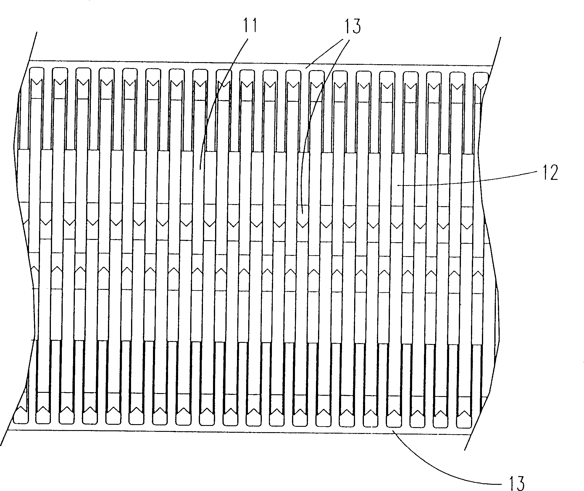
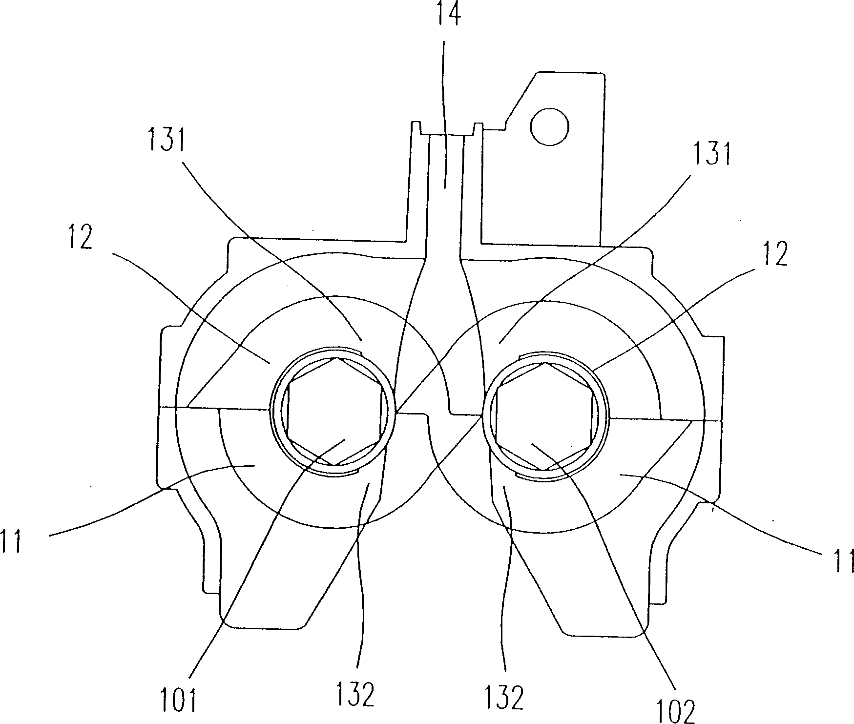
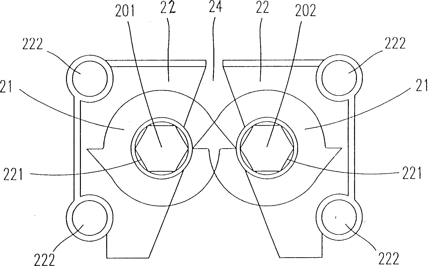
[0020] See figure 2 As shown, it is a schematic cross-sectional view of a preferred embodiment of the shredding device of the present invention. It can be clearly seen from the figure that a shredded paper channel 24 is formed between the first shaft 201 and the second shaft 202 arranged in parallel to provide a passage of paper to be shredded; A plurality of cutting blades (cutters) 21 on the two shafts 202 are directly separated by a gap paper guide 22 with a gap space. And the cutting blade (cutter) 21 that is fixedly fitted on the first shaft 201 and the second shaft 202 can be driven by the first shaft and the second shaft to rotate respectively, and then pass through the shredding passage. 24 of the shredded paper to be cut.

[0021] see you again Figure 3A , 3B As shown, it is a schematic diagram of the appearance structure of the gap paper guide sheet 22 of the present invention, which is manufactured in an integrated manner, and its material can be plastic or me...


PUM


Abstract

The paper breaker device includes a first shaft, a second shaft arranged parallelly with the first shaft, a paper-breaking channel formed between parallelly-arranged said first shaft and second shaft, several cutting knifes which are respectively fixed and cover-mounted on the first shaft and second shaft in the mode of that every both two knifes have a gap space. It is characterized by that several gap paper-guiding sheets are respectively placed in said gap spaces and movably cover-mounted on the first shaft and second shaft, all the gap paper-guiding sheets are made up by adopting integral-forming process, and all the gap-paper-guiding sheets are formed into a continuous surface at paper-breaking channel.

Description

(1) Technical field [0001] The invention relates to a paper shredding device. (2) Background technology [0002] The paper shredder is an indispensable transaction machine in the office, see Figure 1A , 1B As shown, it is a partial structural top view and a schematic cross-sectional view of a conventional paper shredder. It can be clearly seen from the figure that there are gaps between the plurality of cutters (cutters) 11 respectively sleeved on the first shaft 101 and the second shaft 102. The spacers are spaced apart, and the paper guide structure 13 is arranged between the cutters 11 in close fit with the spacers 12 . It can be clearly seen from the cross-sectional view that the upper and lower paper guide structures 131, 132 are tightly sleeved on the surface of the gap 12 to ensure that the paper will not be drawn into the gap after being cut by the cutter 11 through the channel 14. In the gap formed by the gap sheet 12 and the blade 11. However, due to manufactur...

Claims


Application Information

Patent Timeline
IPC IPC(8): B02C18/14
Inventor 林新富
Owner PRIMAX ELECTRONICS LTD
Why Eureka
Try Eureka