

Frequency control method for frequency changer for pumping unit
A frequency control and frequency converter technology, applied in the field of frequency conversion control, can solve the problems of consumption, destruction of frequency converters, energy waste, etc., to achieve the effect of suppressing power generation, reducing energy waste, and avoiding the possibility of destroying frequency converters
- Summary
- Abstract
- Description
- Claims
- Application Information
AI Technical Summary
Problems solved by technology
Method used
Image

Examples
Embodiment 1
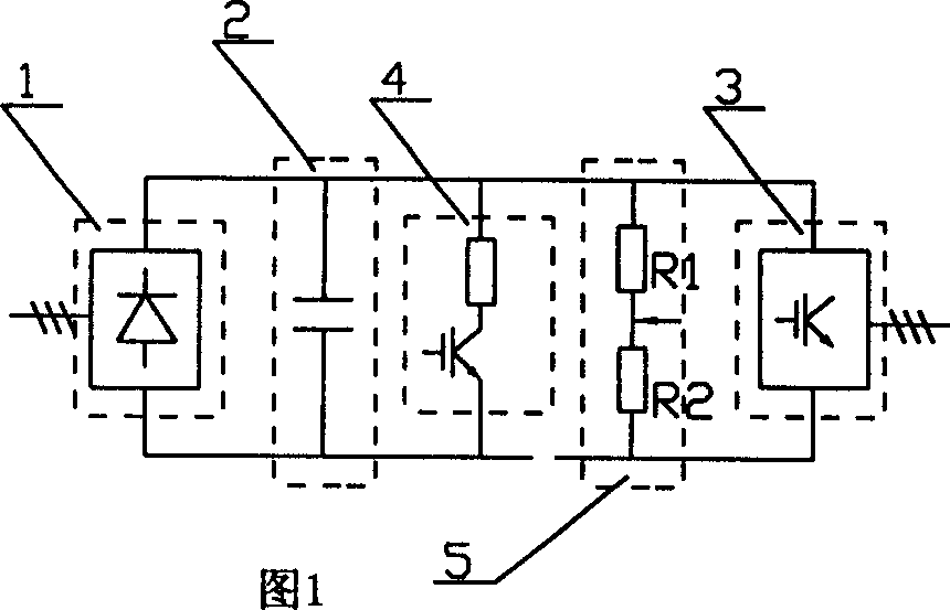
[0023] The method of the present invention is to detect the voltage or current value through the detection unit 5 in the DC circuit of the frequency converter or the output end of the frequency converter, judge whether the motor is in the motoring state or in the power generation state, adjust the output frequency of the frequency converter accordingly, and change the speed of the motor , to reduce or eliminate the consumption of electric energy on the brake unit 4 braking resistors; said adjustment of the output frequency of the frequency converter is to adjust the motor speed by increasing or decreasing the output frequency of the frequency converter so that the average speed of the pumping unit reaches The expected speed value of its operation; specifically: when the motor is in the power generation state, increase the frequency converter frequency, and when the motor is in the electric state, reduce the frequency converter output frequency.
[0024] As shown in Figures 1 an...
Embodiment 2
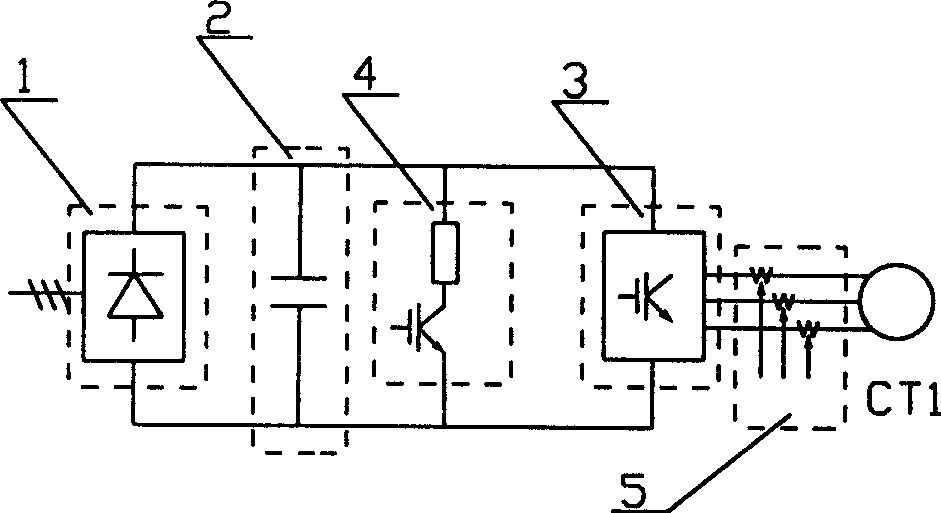
[0030] Such as figure 2 , 5 As shown, the frequency converter is composed of a rectifier 1, an intermediate DC circuit 2, an inverter 3, and a braking unit 4. The voltage detection unit 5 is a current detection unit, and the detection unit 5 for current detection uses three first current sensors CT1 , are electrically connected with the inverter 3 three-phase output terminals respectively; the present embodiment adopts the pumping unit of 37kw electric motor, and the Hall current transformer of 150A is selected as the first current transformer CT1 of the current detection element, and the result is transferred to the computer. control program.
[0031] The specific process of the frequency converter frequency control of the pumping unit in this embodiment (such as Figure 5Shown) is: set the initial current value, the embodiment is 10A, detect the size of the output current of the inverter 3 through the detection unit 5, and judge whether the motor is in the motoring state o...
Embodiment 3
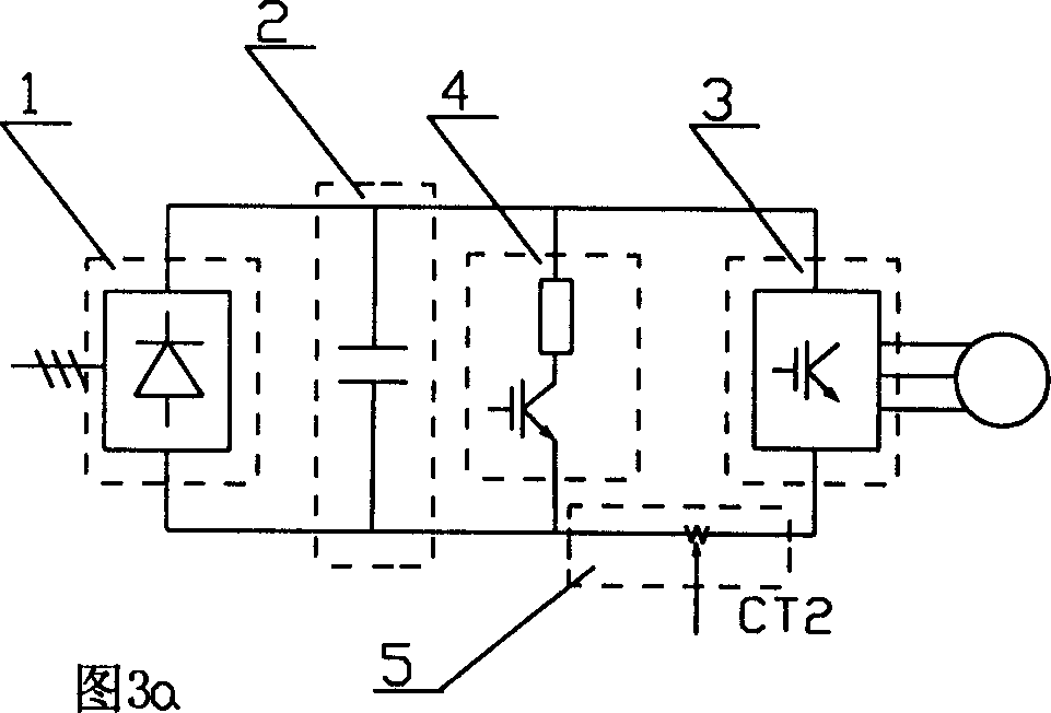
[0035] As shown in Figures 3a and 6, the frequency converter is composed of a rectifier 1, an intermediate DC circuit 2, an inverter 3, and a braking unit 4. The voltage detection unit 5 is a current detection unit, and the detection unit 5 used for current direction detection can be The second current sensor CT2 is connected in series between the inverter 3 and the braking unit 4; the present embodiment adopts a 37kw motor pumping unit, and the second current transformer CT2 selects a 150A Hall current transformer for use, and the result into the control program in the computer.
[0036] The specific process of the frequency control of the frequency converter for the pumping unit in this embodiment is as follows: the current direction of the DC circuit 2 inside the frequency converter is detected by the detection unit 5, and it is judged whether the motor is in the motoring state or in the power generation state; when the current direction is negative, the motor In the power ...
PUM
 Abstract
Description
Claims
Application Information