Fuel cell system
A fuel cell system and fuel cell technology, used in fuel cells, fuel cell additives, transportation fuel cell technologies, etc., can solve problems such as the decline in output efficiency of fuel cell systems, reduce charge and discharge losses, prevent fuel deterioration, The effect of improving output efficiency
- Summary
- Abstract
- Description
- Claims
- Application Information
AI Technical Summary
Problems solved by technology
Method used
Image
Examples
no. 1 Embodiment approach
[0046] 1. Explanation of the overall structure
[0047] [1-1. Overall composition]
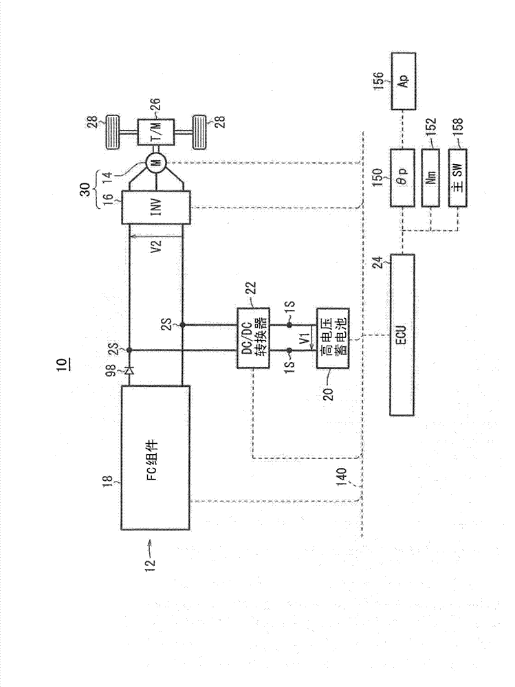
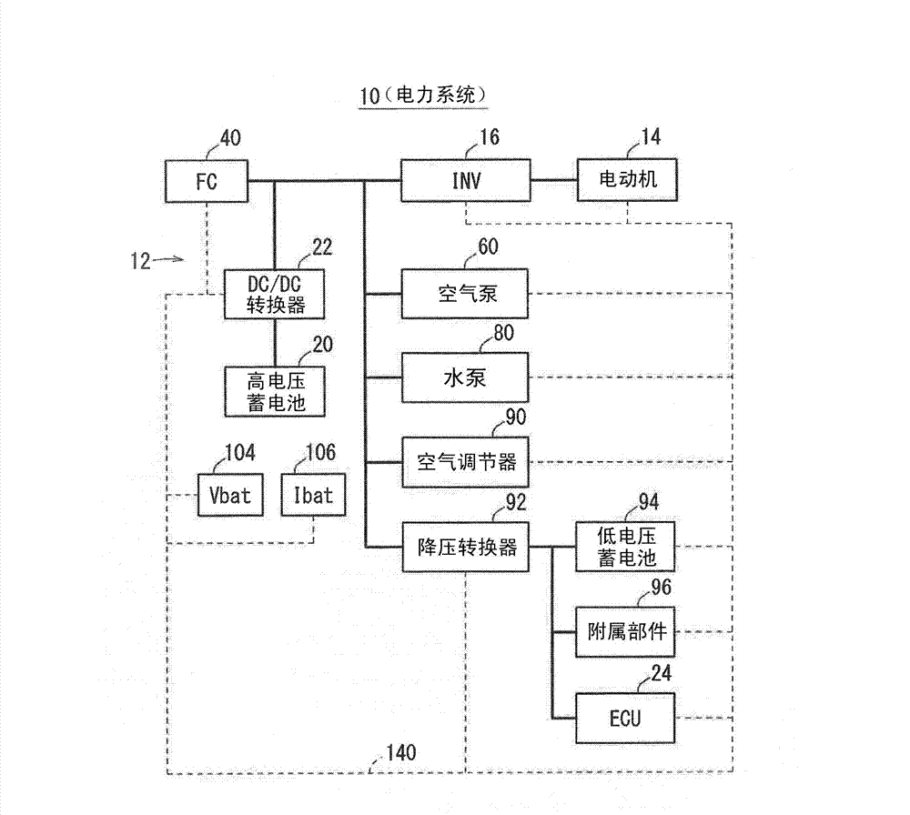
[0048] figure 1 This is a schematic overall configuration of a fuel cell vehicle 10 (hereinafter referred to as "FC vehicle 10") equipped with a fuel cell system 12 (hereinafter referred to as "FC system 12") according to the first embodiment of the present invention. picture. figure 2 is a block diagram of the power system of the FC vehicle 10 . Such as figure 1 as well as figure 2 As shown, the FC vehicle 10 includes a running motor 14 and an inverter 16 in addition to the FC system 12 .
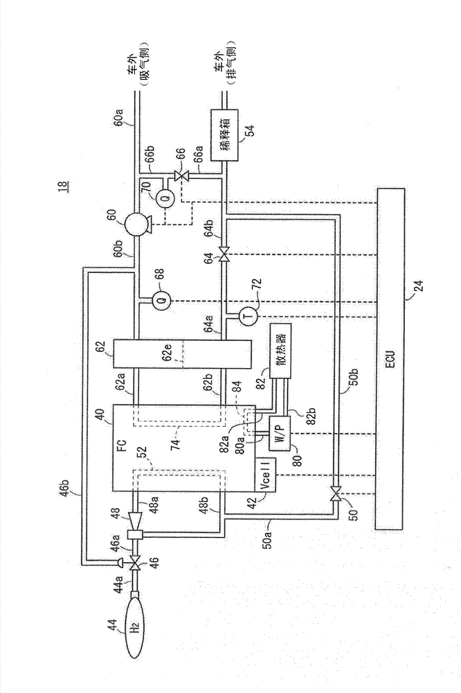
[0049] The FC system 12 has a fuel cell module 18 (hereinafter referred to as "FC module 18"), a high-voltage battery 20 (hereinafter also referred to as "battery 20") (power storage device), and a DC / DC converter 22 , and the electronic control unit 24 (hereinafter referred to as "ECU24").
[0050] [1-2. Drive system]
[0051] The electric motor 14 generates driving force based on electric power...
no. 2 Embodiment approach
[0191] The hardware configuration of the second embodiment is basically the same as that of the first embodiment. Hereinafter, the same reference numerals are used for the same constituent elements. In the second embodiment, the method of energy management of the FC system 12 by the ECU 24 is different from that in the first embodiment.
[0192] 1. Energy management of FC system 12
[0193] Figure 23 It shows that the energy management of the FC system 12 is performed by the ECU 24 in the second embodiment ( Figure 5 The flowchart of S3). and Figure 12 Similarly to step S21, in step S81, ECU 24 determines whether or not the idling power generation suppression mode is selected. Specifically, ECU 24 determines whether or not vehicle speed V is equal to or less than threshold value THV1 and system load Psys is equal to or less than threshold value THPsys1 as conditions of the idling power generation suppression mode. If the vehicle speed V is not equal to or less than th...
PUM
 Abstract
Description
Claims
Application Information
 - R&D
- Intellectual Property
- Life Sciences
- Materials
- Tech Scout
- Unparalleled Data Quality
- Higher Quality Content
- 60% Fewer Hallucinations
Browse by: Latest US Patents, China's latest patents, Technical Efficacy Thesaurus, Application Domain, Technology Topic, Popular Technical Reports.
© 2025 PatSnap. All rights reserved.Legal|Privacy policy|Modern Slavery Act Transparency Statement|Sitemap|About US| Contact US: help@patsnap.com


