
Flyer with vertical launching and other advantages

A vertical take-off and aircraft technology, applied in the field of aircraft, can solve the problems of difficult control, high manufacturing cost, and high cost, and achieve the effect of reducing manufacturing cost, reducing high temperature resistance requirements, and easy adjustment

Inactive Publication Date: 2003-03-19
金洪奎
View PDF0 Cites 7 Cited by
  • Summary
  • Abstract
  • Description
  • Claims
  • Application Information

AI Technical Summary

Problems solved by technology

[0002] In the current aerospace and aviation industry, most of the aircraft are non-vertical take-off and landing; that is, in the process of taking off and landing, they need to use a certain length of runway; It is greatly restricted, and it can only take off and land at the runway that meets its take-off and landing standards; if it cannot land normally due to runway damage, aircraft failure, etc., an emergency landing is required, but in most emergency In the forced landing, all can bring great danger to aircraft and the people and things carried therein; moreover, for laying and maintaining its runway, it will also cost a lot, which is not conducive to effectively controlling the cost of use; therefore, people use it in civil and military Aviation and other aspects are researching and partially using vertical take-off and landing aircraft; for now, among the vertical take-off and landing aircraft put into use in various countries in the world, British Harrier fighter jets and American Lockheed-Martin Corporation produce The X-35F fighter jet is the most advanced. Both of the above two fighters use jet engines, and the temperature of the jet outlet is extremely high. Therefore, the material of the jet pipe is required to have very strict high temperature resistance; It is realized by increasing the engine power and slowly rotating the exhaust port angle. However, to realize this kind of control and structure, pilots are required to operate and have high control skills. To control the aircraft; moreover, the requirements for the manufacture of this structure are also very strict; thus, its manufacturing cost is very high, its operation is difficult, and its scope of application is greatly limited; it is not suitable for a wide range of commercial fields such as civil aviation. application

Method used


Image

  • Flyer with vertical launching and other advantages
  • Flyer with vertical launching and other advantages
  • Flyer with vertical launching and other advantages

Examples


Embodiment Construction

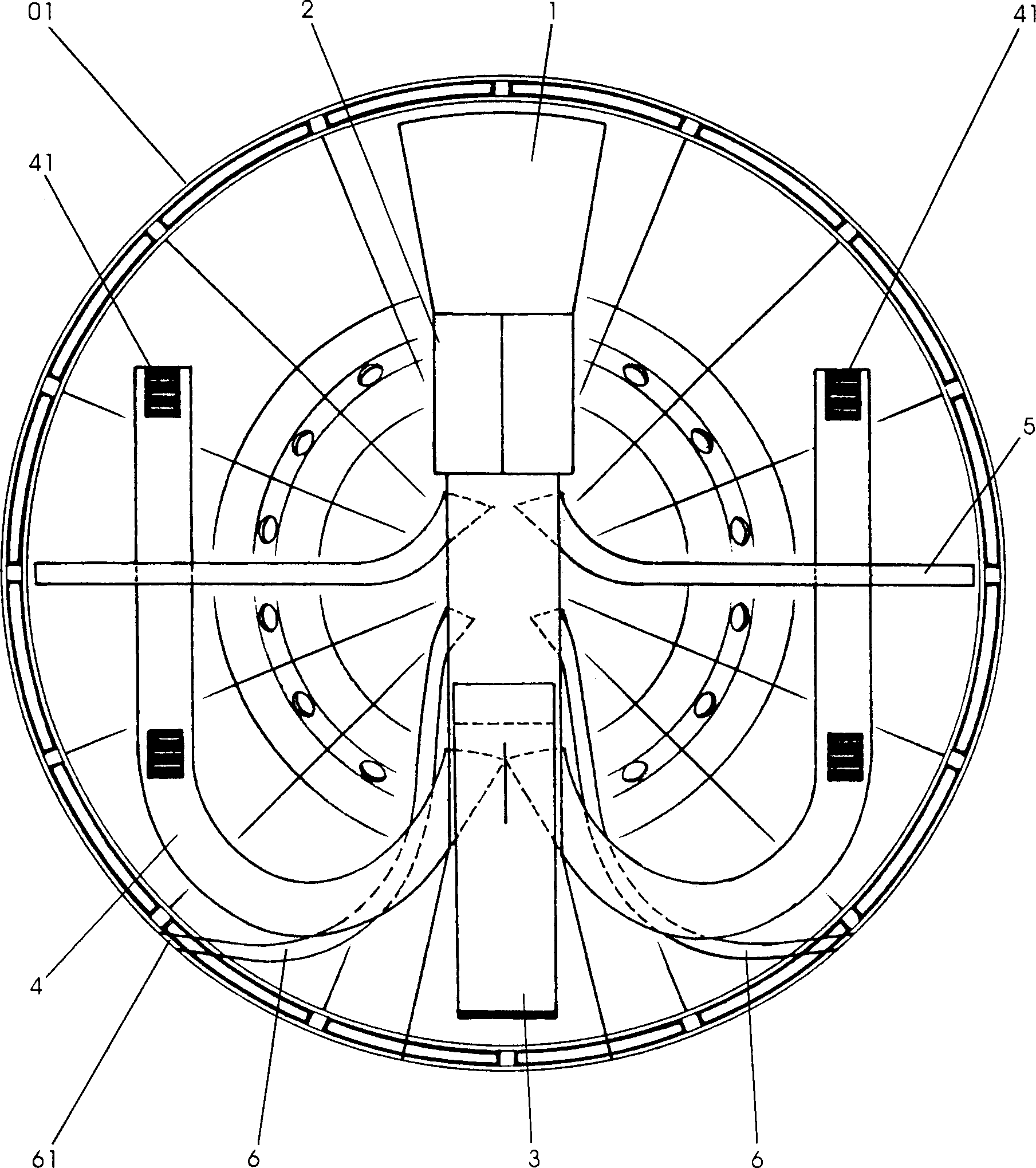
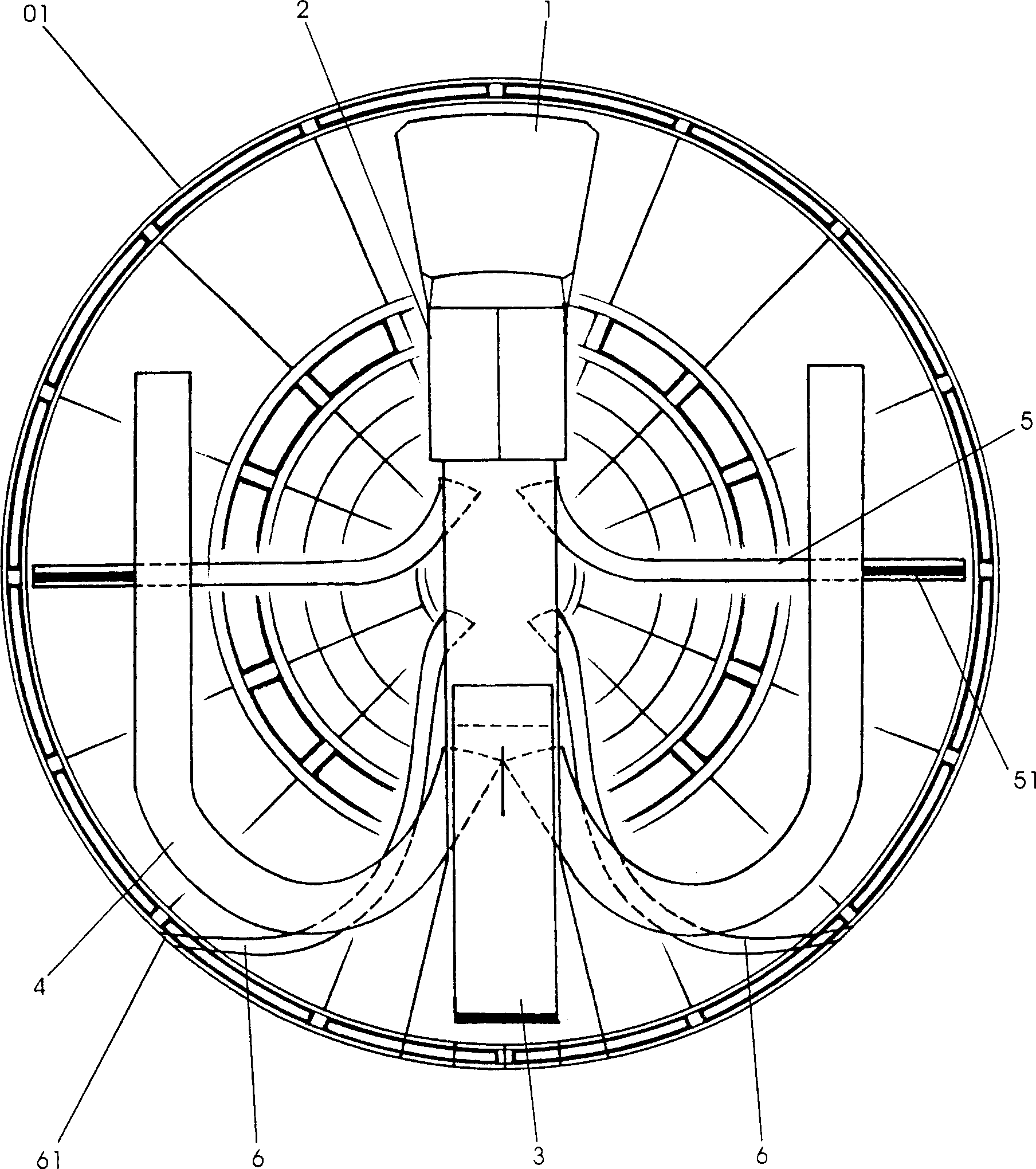
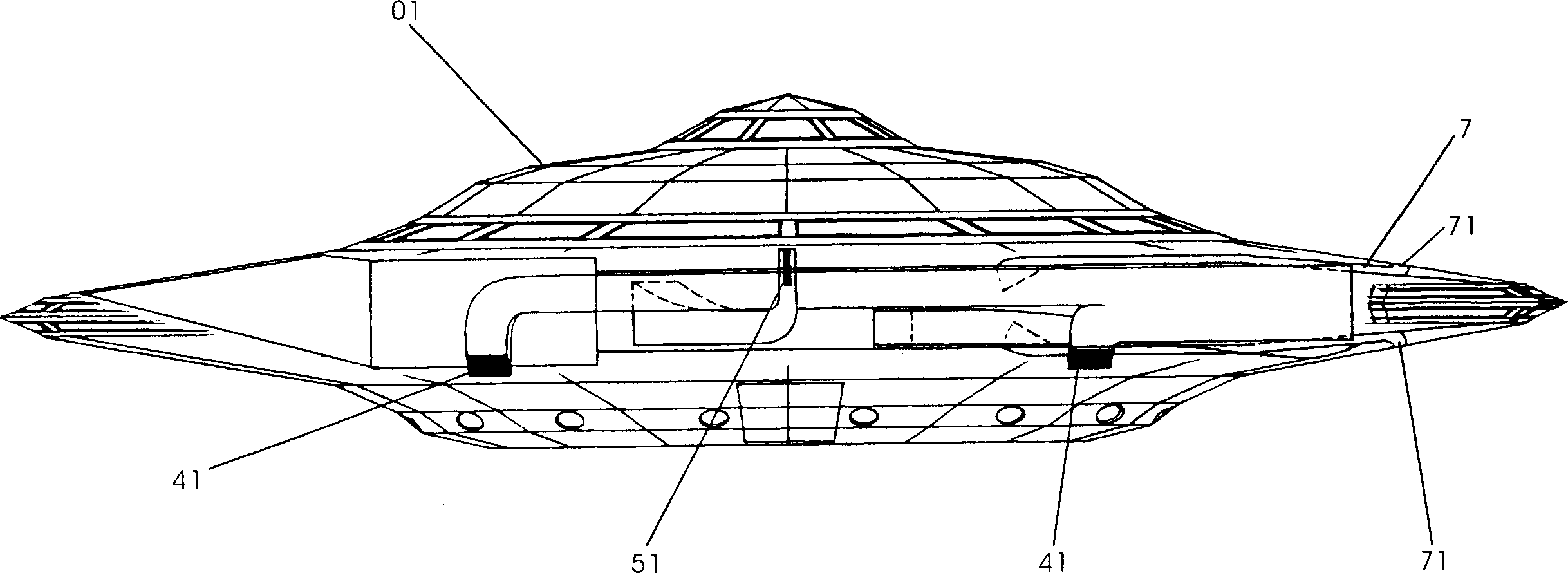
[0019] See attached Figures 1 to 4 , the front end of the body 01 of the disc shape or other shapes of the aircraft of the present invention is provided with an air inlet 1, and the turbofan engine 2 is connected between the air inlet 1 and the main exhaust pipe 3; two can be set here Or an engine 2, depending on the field of use and requirements; the straight main exhaust pipe 3 is arranged along the center of the body 01, and is connected with the main exhaust pipe 3 to provide an exhaust branch pipe for vertical take-off and landing of the aircraft 4; when the body 01 of the aircraft is naturally horizontal, the exhaust branch pipe 4 is distributed in a W shape in the horizontal direction; the exhaust port 41 opening at the tail end is downward, and the number of exhaust ports 41 can be set to one or two on each side. One; at this phase connection, be provided with a dividing plate 8 that divides the main exhaust pipe 3 into two ways; The air flow flows to the rear of the...


PUM


Abstract

The present invention relates to aeronautical and astronautic technology, and aims at solving the problems of vertical launching, etc. The technological scheme includes the air intake in front end of the main body, engine between the air intake and the main exhaust pipe, the straight main exhaust pipe set in the center, the branched exhaust pipe for vertical launching connected to the main exhaust pipe and with downward opening at the tail end. The present invention is simple in structure, low in cost and easy to control, and may be used widely in civil and military aviation.

Description

Technical field: [0001] The invention relates to the technical field of aerospace and aviation equipment, in particular to an aircraft that can quickly realize vertical take-off and the like through simple manipulation. Background technique: [0002] In the current aerospace and aviation industry, most of the aircraft are non-vertical take-off and landing; that is, in the process of taking off and landing, they need to use a certain length of runway; It is greatly restricted, and it can only take off and land at the runway that meets its take-off and landing standards; if it cannot land normally due to runway damage, aircraft failure, etc., an emergency landing is required, but in most emergency In the forced landing, all can bring great danger to aircraft and the people and things carried therein; moreover, for laying and maintaining its runway, it will also cost a lot, which is not conducive to effectively controlling the cost of use; therefore, people use it in civil and ...

Claims


Application Information

Patent Timeline
Patent Type & Authority Applications(China)
IPC IPC(8): B64C29/04
Inventor 金洪奎
Owner 金洪奎
Learn More