Modular formwork members

A formwork component and group technology, which is applied to building components, building structures, floor slabs, etc., can solve the problems of elongated construction period, long period and high cost.

Inactive Publication Date: 2003-03-19
湖南邱则有专利战略策划有限公司
View PDF1 Cites 186 Cited by
  • Summary
  • Abstract
  • Description
  • Claims
  • Application Information

AI Technical Summary

Problems solved by technology

However, the construction of this kind of reinforced concrete shear key type two-way hollow slab is complicated, troublesome, and takes a long period of time. It is necessary to first construct the cast-in-place lower ribs. , and then put the prefabricated upper formwork, which will inevitably lengthen the construction period. Generally,

Method used


Image

  • Modular formwork members
  • Modular formwork members
  • Modular formwork members

Examples


Embodiment Construction

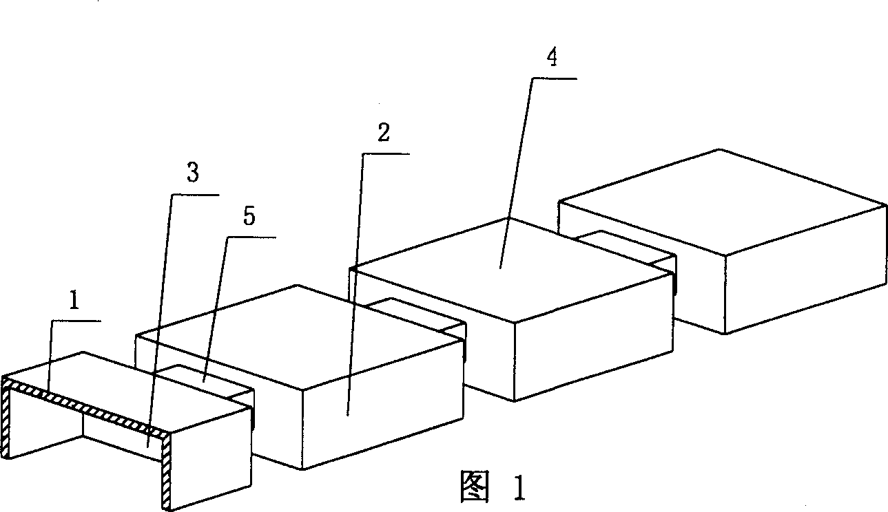
[0072] The present invention will be further described below in conjunction with the accompanying drawings and embodiments.

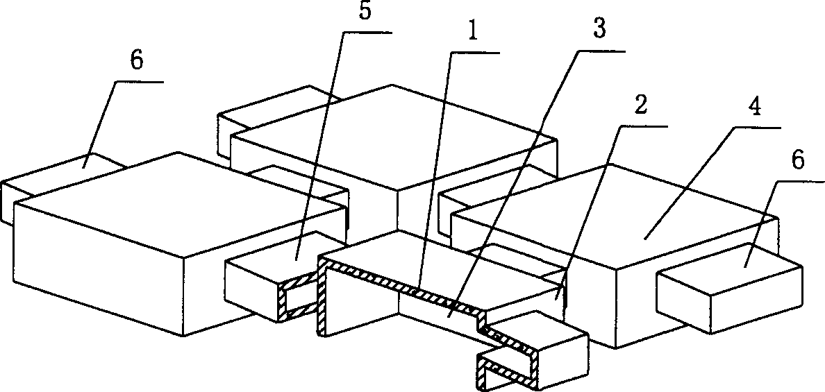
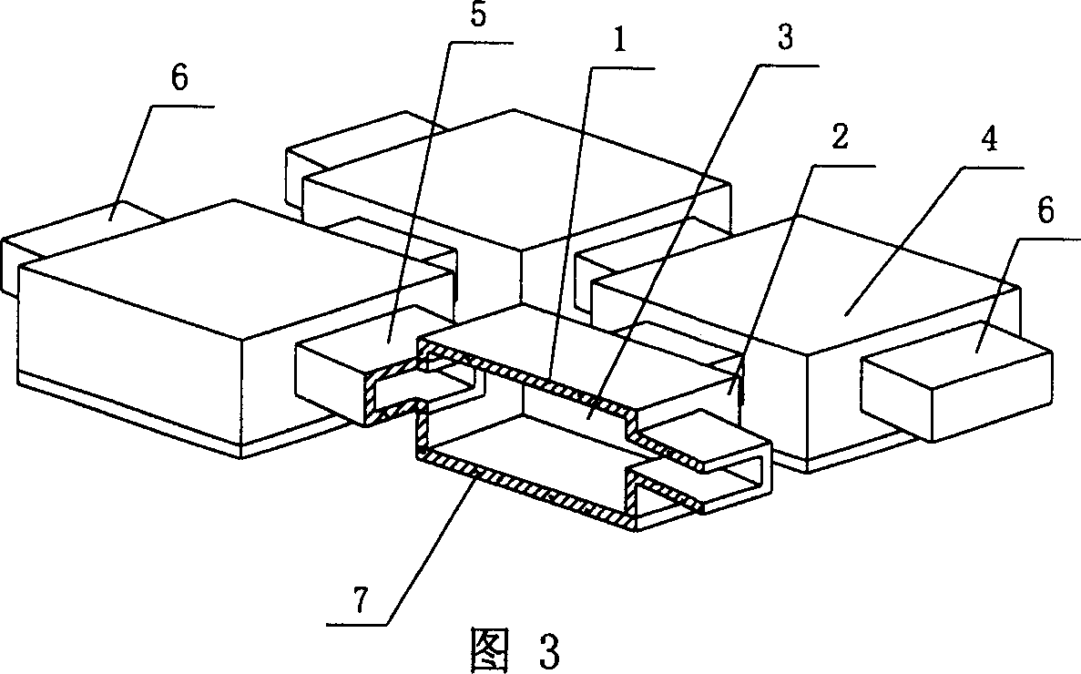
[0073] As shown in the accompanying drawings, the present invention includes a formwork upper plate 1 and surrounding side walls 2, and the upper plate 1 and the surrounding side walls 2 form a formwork 4 with a cavity 3, which is characterized in that at least two formworks 4 are in at least one At least one of the surrounding side walls 2 has a connecting pipe 5 to connect the mold shells 4 to each other as a whole. Fig. 1 is a schematic structural diagram of Embodiment 1 of the present invention. Among Fig. 1, 1 is the upper plate of the formwork, 2 is the surrounding side wall, 3 is the cavity, 4 is the formwork, and 5 is the connecting pipe. In the following drawings, those with the same number have the same description. In FIG. 1 , four formworks 4 are connected to each other as a whole through the connecting pipes 5 of the surrounding side walls...


PUM


Abstract

The modular formwork member includes top plate and side walls to constitute cavity formwork. The present invention features that there is at least one connection tube between the adjacent walls of two formworks. When the modular formwork members are used in hollow stringboard, there will be vertical rib formed around the connection tube via in-situ cast and shearing bonding formed in the empty part between the formwork members, so that the hollow stringboard can form reinforced concrete-shearing bonding type bi-directional hollow large board in only once deposition. The present invention has simple formwork, simple construction, low cost and short construction period, and the member has high strength, simple structure, low cost and easy construction.

Description

(1) Technical field [0001] The invention relates to a group form shell component for cast-in-situ concrete hollow structures. (2) Background technology [0002] At present, the building (roof) structure is the most widely used cast-in-place concrete hollow structure. The common structural forms include beam-slab or ribbed floor, prestressed slab structure, and non-prestressed slab structure. These structures have their own characteristics. Insurmountable shortcomings. In general, the height of the beam-slab floor structure needs to be 1 / 10-1 / 12 of the span of the frame beam section, so the structure takes up a lot of space, which is not convenient for the pipeline layout in the building. Take up interior space. In order to meet the requirements of indoor space, the height of the storey must be increased in the structure. When the height of the storey is limited, only wide flat beams no larger than the column width can be used to meet the rigidity requirements. At this time...

Claims


Application Information

Patent Timeline
IPC IPC(8): E04B5/36
Inventor 邱则有
Owner 湖南邱则有专利战略策划有限公司
Why Eureka
Try Eureka