
Honeycomb-shape mouthpiece forextruding for mation and production method thereof

一种挤压成形、制造方法的技术,应用在金属挤压的成型工具、金属挤压、制造工具等方向,能够解决加工精度不够、蜂窝状构造体50不良、表面粗糙度差异等问题,达到高尺寸精度和强度的效果

Inactive Publication Date: 2003-03-26
NGK INSULATORS LTD
View PDF1 Cites 10 Cited by
  • Summary
  • Abstract
  • Description
  • Claims
  • Application Information

AI Technical Summary

Problems solved by technology

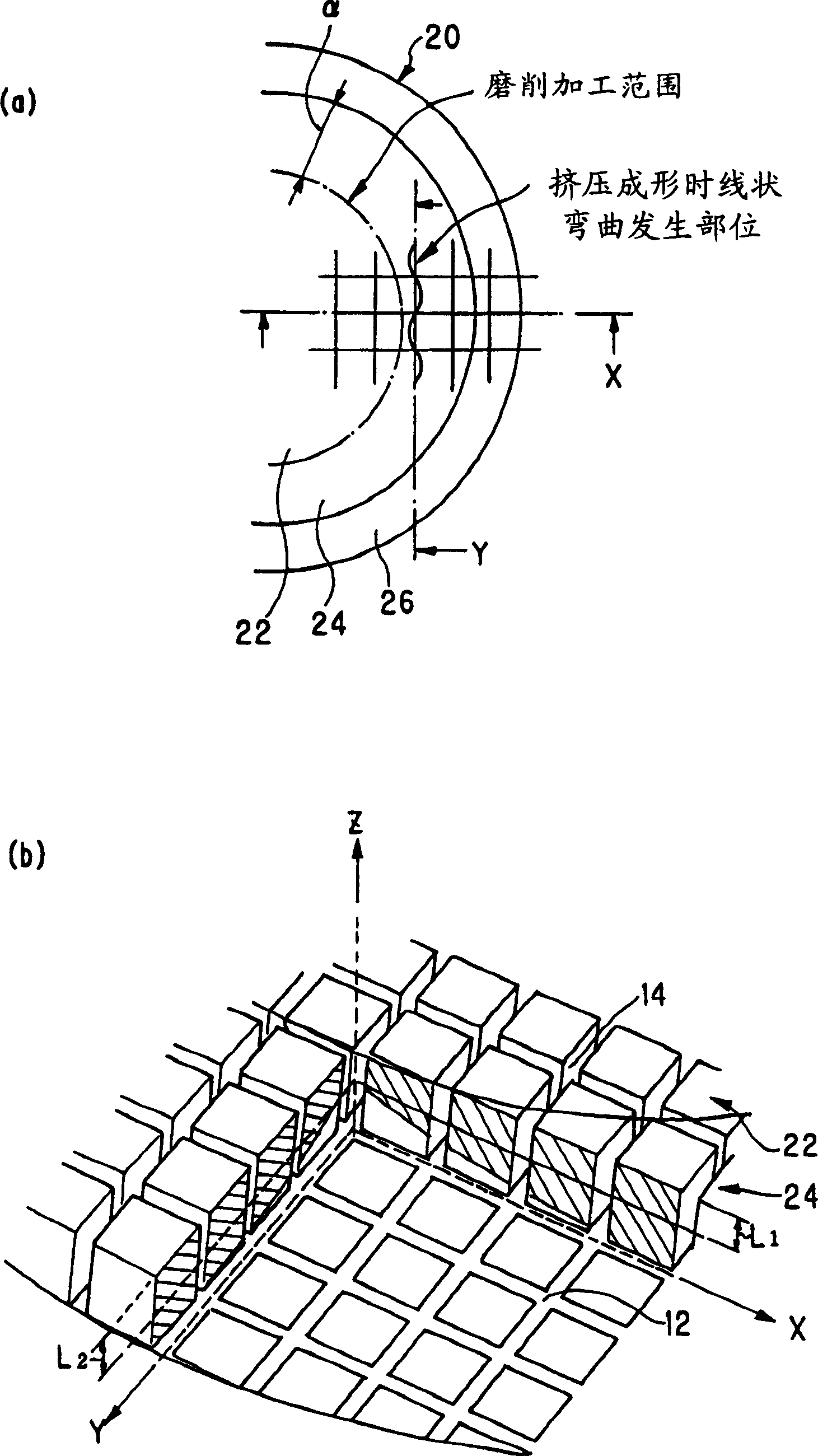
[0013] However, since the above-mentioned mouthpiece 10 has a different slit width from the inner portion 22 and the outer peripheral portion 24, when only the disc-shaped grinding wheel is used for grinding, drawing, for example, near the boundary between the inner portion 22 and the outer peripheral portion 24 Figure 5 (b) The grinding wheel depth of cut trace and the trajectory of the contact arc shown in [ Figure 5 The hatched part in (b)], a difference is generated between the slit depth L1 of the wide part in the X direction and the slit depth L2 of the wide part in the Y direction
[0014] Therefore, the honeycomb structure made of ceramics extruded with the above-mentioned mouthpiece such as Image 6 , Figure 7 As shown, there is a problem that a linear bend (cell deformation defect) 30 occurs at the boundary between the outer peripheral cell partition wall 2a and the basic cell partition wall 2b.
[0015] Moreover, there is also such a problem that the wider slit width portion of the outer peripheral portion 24 is subjected to electric discharge machining with a carbon electrode, especially when making a mouthpiece of 2 to 3 mil (about 0.05 to 0.075 mm) or less. The machining accuracy of the slit width (±2 to 3 μm) is insufficient, and there is a difference in the surface roughness of the machined surface between the grinding process and the electric discharge machining, and the ratio of the surface roughness of the outer peripheral portion 24 to the inner portion 22 is as large as 10. Above, so the extrusion pattern of the mouthpiece is not good
[0016] Moreover, the inner portion 22 and the outer peripheral portion 24 of the mouthpiece 10 have different slit widths, which are related to the fluidity of the molding material. However, when extrusion molding is performed directly, the molding speed of the outer peripheral portion 24 is faster than that of the inner portion 22. , therefore, if Figure 8 As shown, the pattern will be involved, and there is a problem that the honeycomb structure 50 is prone to defects.

Method used


Image

  • Honeycomb-shape mouthpiece forextruding for mation and production method thereof
  • Honeycomb-shape mouthpiece forextruding for mation and production method thereof
  • Honeycomb-shape mouthpiece forextruding for mation and production method thereof

Examples


Embodiment

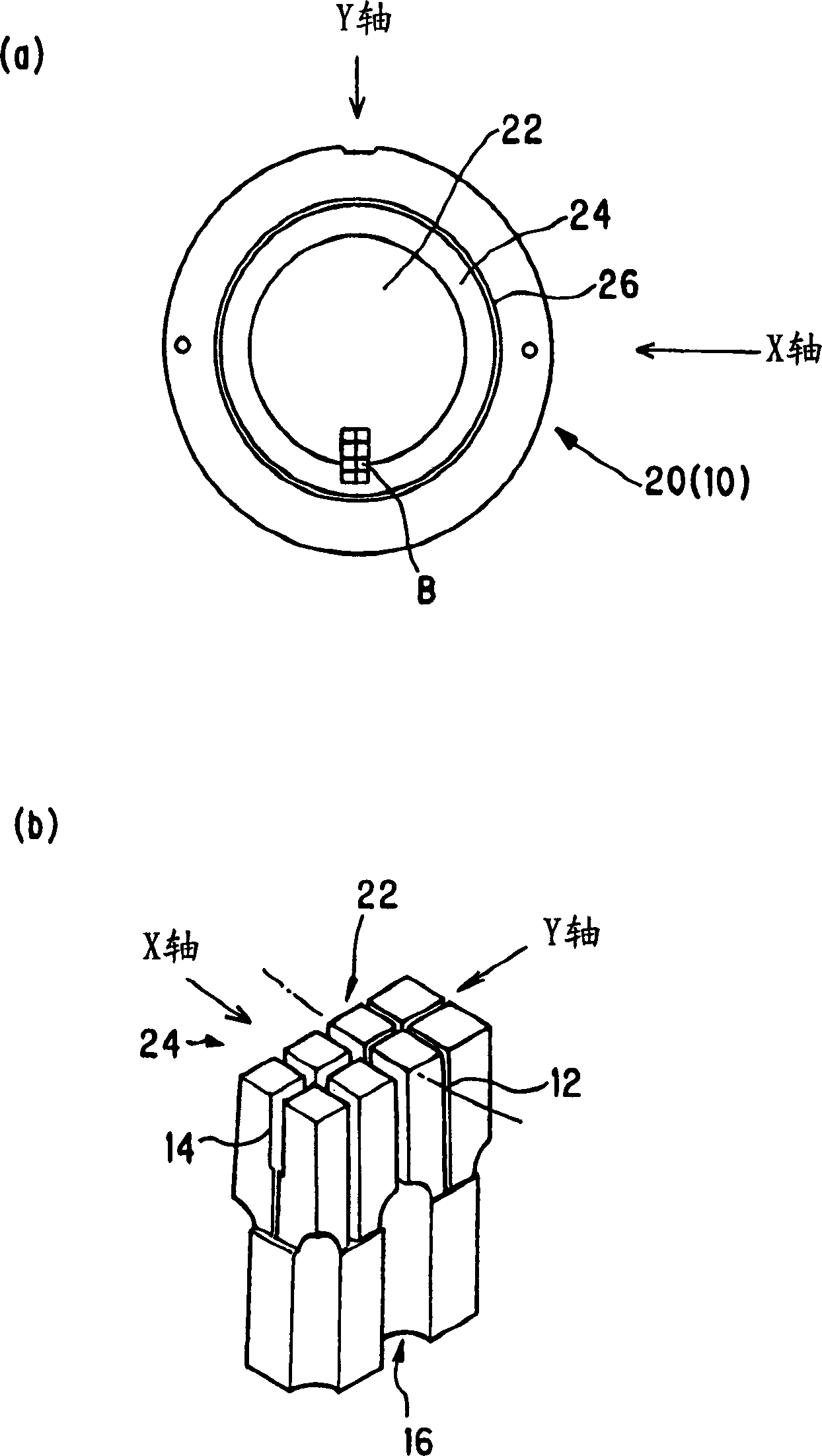
[0063] 900(Psi(unit / inch 2 )), mouthpiece for product outer diameter φ100 (see figure 1 ),Such as figure 2 As shown in (b), all the slits 12 and 14 are formed into a lattice shape by grooving with a grinding wheel, and the cutting depth in the Z direction is appropriately adjusted while grinding so that the width of each intersection point in the X and Y directions is wider. The absolute value difference of the slit depth at the top (|L 1 -L 2 |) less than 0.05mm.

[0064] At this time, mouthpieces (Examples 1 and 2, Comparative Examples 1 and 2) having the surface roughness (Ra) of the slits 12 and 14 in the outer peripheral portion and inner portion as shown in Table 1 were prepared.

[0065] Next, the above-mentioned mouthpiece is coated with Ni plating to form figure 1 The specified slit width shown in (b) [the width of the slit 12: 50 μm, the width of the slit 14: 80 μm (about 10 units from the inner side 22)], and then, as image 3 As shown, the slit exit surfac...


PUM

PropertyMeasurementUnit
roughnessaaaaaaaaaa
roughnessaaaaaaaaaa
roughnessaaaaaaaaaa

Abstract

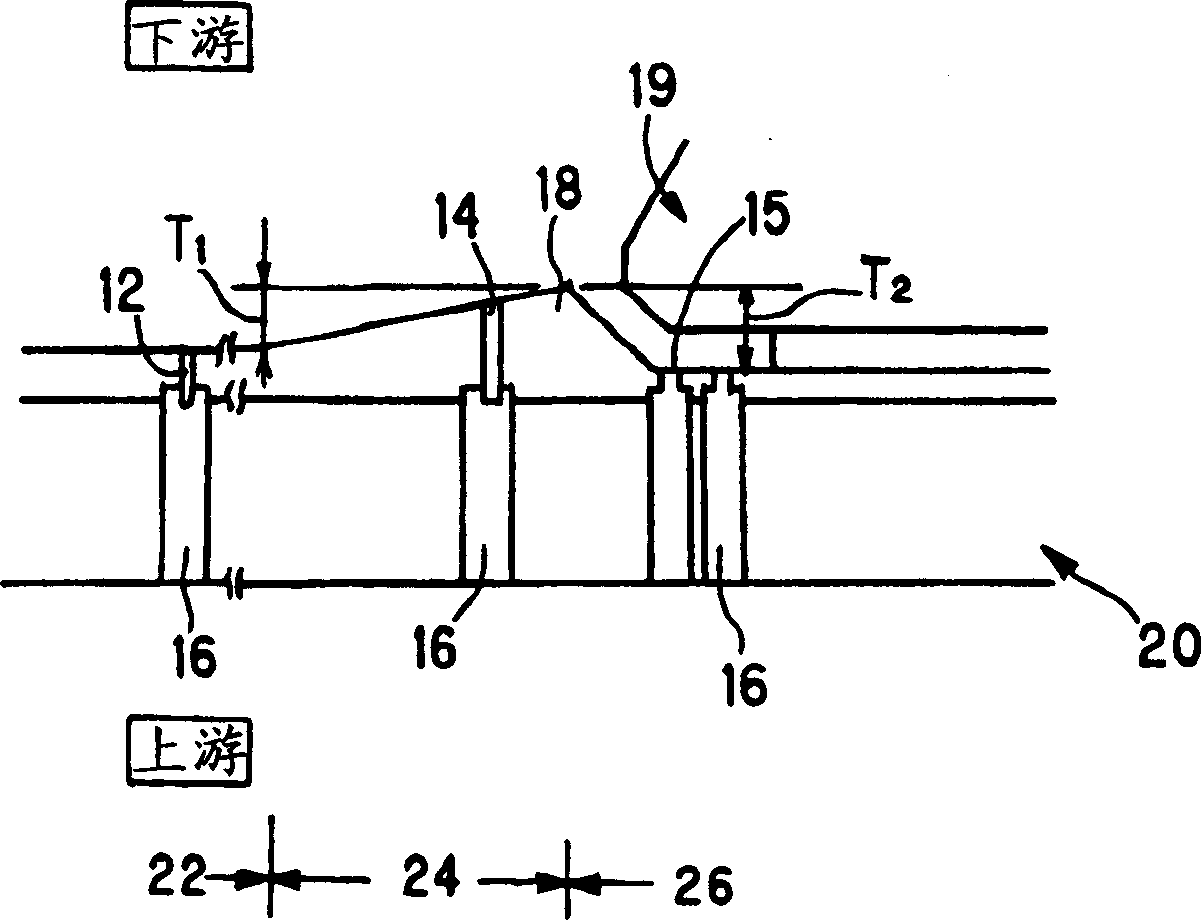
The invention provides a mouthpiece for honeycomb extrusion molding capable of imparting higher dimensional accuracy and strength even in a honeycomb structure wherein partition walls for forming cells are thin and the density of cells are different by region and small, and a method for manufacturing the same. The mouthpiece 20 is equipped with a back hole 16 for introducing a molding raw material and slits 12 and 14 for extruding the molding raw material and adapted to the extrusion molding of a honeycomb structure. The mouthpiece 20 comprises an inside part 22, an outer peripheral part 24 and an outermost peripheral part 26 and the width of the slit 14 arranged to the outer peripheral part 24 is larger than that of the slit 12 arranged to the inside part 22. When the surface roughness (Ra) of the slits 12 and 14 of the outer peripheral part and the inside part is not more than 0.1 mu m or exceed 0.1 mu m, the relation of the surface roughness (a) of the slit of the inside part 22 and the surface roughness (b) of the outer peripheral part 24 is set to 0.1 B29C 47 / 12 B28B 3 / 26 9 7 1 2002 / 9 / 19 1404935 2003 / 3 / 26 100436106 2008 / 11 / 26 2008 / 11 / 26 2008 / 11 / 26 NGK Insulators, Ltd. Japan Miyasaki Sei Okada Koji zhang tianan 72001 The Company Ltd. of the Chinese Patent Agency (Hong Kong) Zi Building 22, Yingjun Centre, No.23, Gangwan Road, Hong Kong Wanzi Japan 2001 / 9 / 19 285669 / 01

Description

technical field [0001] The invention relates to a mouthpiece for honeycomb extrusion molding and a manufacturing method thereof. Background technique [0002] In the past, catalysts for purifying automobile exhaust were carried on the surface of each cell of a ceramic honeycomb carrier (honeycomb structure) to form a so-called honeycomb catalyst. ) direction is high, so the structure of clamping in the axial direction of the honeycomb carrier is adopted. In this case, in order to prevent the outer peripheral part from being damaged when it is clamped in the axial direction, the cell partition walls (ribs) on the outer peripheral part are thicker than those inside, thereby improving the axial compressive strength of the honeycomb carrier. [0003] However, recently, with the trend of higher engine output, it is required to reduce the pressure loss of the honeycomb catalyst, and with the strengthening of exhaust gas restrictions, it is required to effectively use the entire c...

Claims


Application Information

Patent Timeline
Patent Type & Authority Applications(China)
IPC IPC(8): B28B3/26B28B3/20B29C48/11B29C48/30B29C48/32
CPCB29L2031/60Y10T29/49995B29C47/12B23H9/00B28B3/269B29C47/0028B23H2200/30B29C48/11
Inventor 宫崎诚冈田幸司
Owner NGK INSULATORS LTD
Learn More