Switch device for receiving/emitting electromagnetic wave device

A technology for transmitting waves and stimulating devices, which is applied in the field of wireless transmission, and can solve problems such as increased receiver noise temperature, significant additional costs, and expensive switches

Inactive Publication Date: 2003-04-02
THOMSON LICENSING SA
View PDF0 Cites 1 Cited by
  • Summary
  • Abstract
  • Description
  • Claims
  • Application Information

AI Technical Summary

Problems solved by technology

[0005] Therefore, this switch is expensive as a result of the price of the diodes and production costs, and, because of the offset circuit and the supply adder / subtractor circuit, the switch is bulky
Also, introduces power losses that do not take into account: losses in adder / subtractor circuits, losses in DC blocking, losses in diodes
These losses lead to an increase in the noise temperature of the receiver at the receive end, and at the transmit side, there are dry losses of the transmitted energy, which requires the power amplifier to be oversized, possibly at very significant additional cost

Method used


Image

  • Switch device for receiving/emitting electromagnetic wave device
  • Switch device for receiving/emitting electromagnetic wave device
  • Switch device for receiving/emitting electromagnetic wave device

Examples


Embodiment Construction

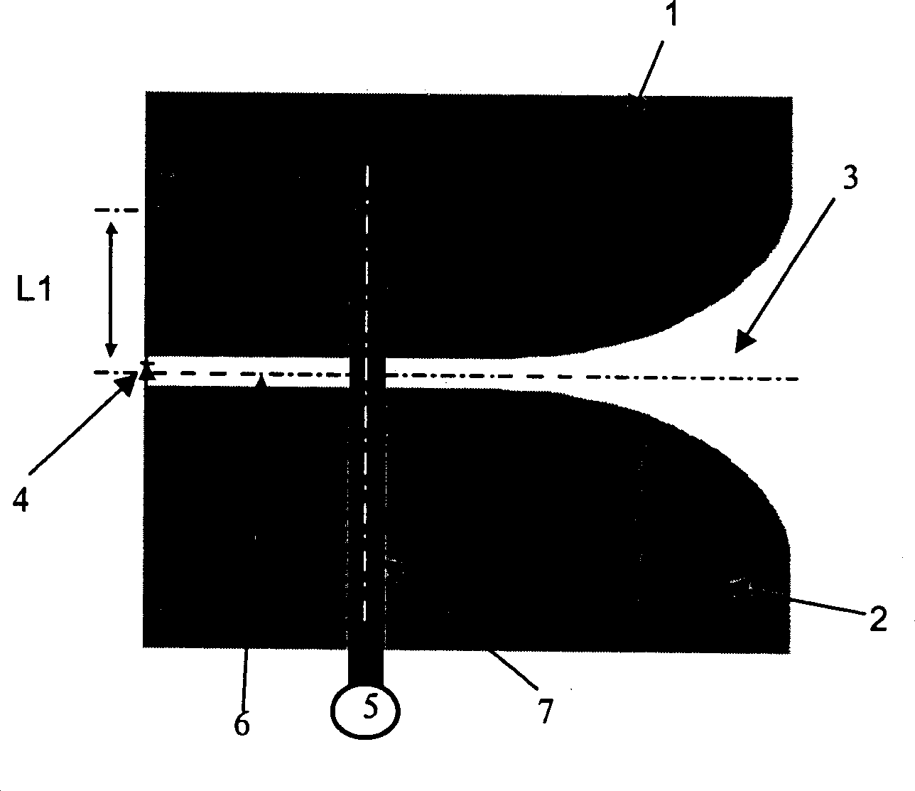
[0021] figure 1 The Vivaldi type antenna printed on the substrate 3 is shown. The structure and performance of Vivaldi antennas are well-known to those skilled in the art and are described in the following documents, "IEEE Transactions on Antennas and Propagation" by S. Prasad and S. Mahpatra, Volume 2 AP-31, May 1983 , And "Study of discontinuities in open waveguide-application toimprovement of radiating source model" by A. Louzir, R. Clequin, S. Toutain and P. Gelin, Last. Ura CNRS No. 1329. figure 1 The power supply of the Vivaldi antenna is based on the transition from the microstrip line 7 to the slot 6. In order to optimize the energy transmission from the microstrip to the slit, the unopened end of the slit extends vertically to the microline with a length of approximately L2. At the operating frequency of the microstrip line k'λs / 4, λs = λ0 / √εlreff (λ0 is the vacuum In the wavelength, εlreff is the effective relative permittivity of the slit), and K is an odd integer. F...


PUM


Abstract

The present invention relates to a device for receiving and / or transmitting signals comprising an assembly of n means for receiving and / or transmitting waves with longitudinal radiation of the printed slot-antenna type, where n is an integer greater than or equal to one, and an excitation means of the microstrip-line type coupled to at least one slot line. The present invention is characterized in that it comprises a switching device which acts by controlling the coupling between the microstrip line and at least one slot line.

Description

Technical field [0001] The invention relates to a switch device for receiving and / or transmitting signal equipment, which is particularly suitable for the field of wireless transmission. Background technique [0002] In the known high-efficiency wireless transmission system used in the home environment, the signal sent by the transmitter reaches the receiver along many isolated paths. At the receiver end, it may cause attenuation and distortion of the transmitted signal, and at the same time cause loss or attenuation of the transmitted information. In order to overcome this shortcoming, horns, reflectors or arrays of directional antennas are often used. These antennas are used for transmitting and / or receiving, and can prevent and weaken the attenuation formed by complex paths. In addition to the gain obtained from the directional antenna, on the one hand, spatial filtering can reduce the number of complex paths, that is, reduce the attenuation, on the other hand, reduce the impa...

Claims


Application Information

Patent Timeline
Patent Type & Authority Applications(China)
IPC IPC(8): H01Q23/00H01Q3/24H01Q13/00H01Q13/02H01Q13/08H01Q13/10H01Q21/20
CPCH01Q21/205H01Q13/085H01Q3/242
Inventor 弗兰克·图多菲利普·米纳尔阿里·卢齐弗朗索瓦·勒博尔泽
Owner THOMSON LICENSING SA
Why Eureka
Try Eureka