Electric fuel pump for vehicle

A fuel pump, electric technology, applied in liquid fuel feeders, liquid fuel engines, pumps, etc., can solve the problems of increased labor and expensive pumps.

Inactive Publication Date: 2003-04-30
KYOSAN DENKI KABUSHIKI KAISHA +1
View PDF0 Cites 18 Cited by
  • Summary
  • Abstract
  • Description
  • Claims
  • Application Information

AI Technical Summary

Problems solved by technology

Therefore, since these holes must be separately formed on the cover

Method used


Image

  • Electric fuel pump for vehicle
  • Electric fuel pump for vehicle
  • Electric fuel pump for vehicle

Examples


Embodiment Construction

[0032] Detailed description of the preferred embodiment

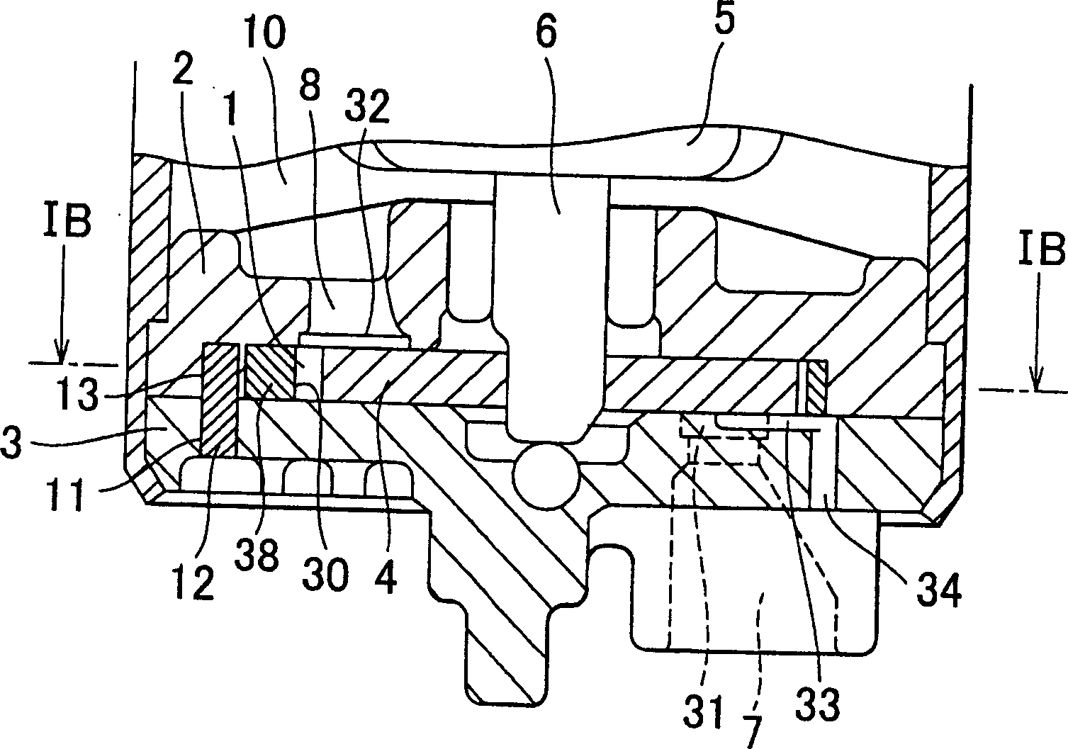
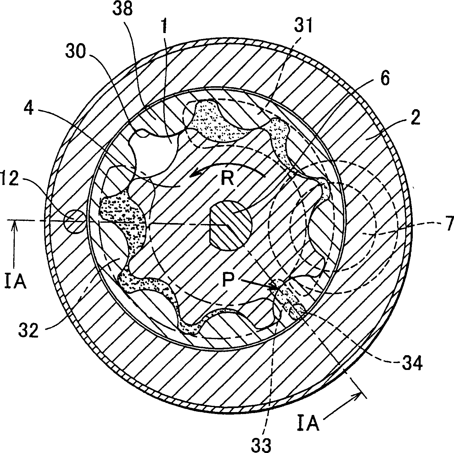
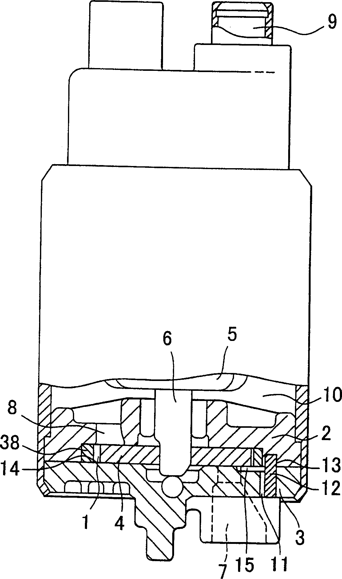
[0033] Embodiments of the present invention will be described with reference to the accompanying drawings. Figure 1A and 1BAn embodiment of a vehicle electric type fuel pump according to the present invention is shown. Figure 1A is along Figure 1B A sectional view taken on the median line IA-IA, Figure 1B is along Figure 1A Sectional view taken at midline IB-IB. figure 2 is a sectional view of a main part of another embodiment of the vehicle electric type fuel pump according to the invention to be made.

[0034] The overall structure of the pump device according to the present invention is the same as that shown in FIGS. 9A and 9B described above. The pump body part is constituted by combining the housing 2 and the cover 3, the housing 2 rotatably accommodates an external rotor 38, thereby forming the pump chamber 1 on the inner peripheral surface, the cover 3 is pressed against the lower surface of the housing...


PUM


Abstract

At a boundary area between a high-pressure portion in which a discharge port of a fuel pump is disposed and a low-pressure portion in which an intake port is disposed, a pressure relief groove extending along the boundary area is formed so as to be communicated with the outside of the pump by means of pressure relief hole. Alternatively, a slit is formed communicated with the outside. Accordingly, a fuel at a high-pressure area portion can be drained with reliability. Further, by communicating the above pressure relief groove with a positioning pin insertion port, a single hole can serve both as a positioning pin insertion hole and a pressure relief hole.

Description

technical field [0001] The present invention relates to a vehicle motor-driven type fuel pump housed in a vehicle fuel tank, and more particularly, to an electric type fuel pump for a vehicle for reliably preventing fuel compressed by one compression stroke of the pump from being used as Vapor enters the port side and further allows a single hole to serve both as a locating pin to perform positioning when the housing and cover are assembled, and as a relief hole to relieve pressure in the pump chamber. Background technique [0002] Recently, an in-tank type motor-driven fuel pump installed in a fuel tank is used as a fuel pump that supplies fuel to a motor of a vehicle. Widely used among them is a fuel pump suspended from a flange member fastened to a hole in the upper wall of the fuel tank. Also used is an integral type fuel pump in which a filter or the like is incorporated. [0003] In these fuel pumps, as shown in the sectional view of the pump part in FIG. A bottom s...

Claims


Application Information

Patent Timeline
IPC IPC(8): F04C2/08F04C2/10
CPCF04C2/102F04C2/088
Inventor 川崎弘秋木村明広海老原嘉男
Owner KYOSAN DENKI KABUSHIKI KAISHA
Why Eureka
Try Eureka