Gas insulation switchgear

A gas-insulated switch and insulating gas technology, applied in the direction of electric switches, high-voltage/high-current switches, electrical components, etc., can solve the problem of damage to the appearance of gas-insulated switchgear, complex manufacturing and cost of gas-insulated switchgear, and no consideration of providing absorption agent and the formation of hand holes etc.

Inactive Publication Date: 2003-05-28
HITACHI LTD
View PDF0 Cites 4 Cited by
  • Summary
  • Abstract
  • Description
  • Claims
  • Application Information

AI Technical Summary

Problems solved by technology

Although prior art methods arrange impurity trapping containers at vibration nodes, gas insulated switchgear requires absorbers to be placed in all gas chambers, and for inspection of circuit breakers, gas insulated switchgear must be provided with hand holes
[0007] However, prior art methods do not consider providing absorbent and forming hand holes

Method used


Image

  • Gas insulation switchgear
  • Gas insulation switchgear
  • Gas insulation switchgear

Examples


Embodiment Construction

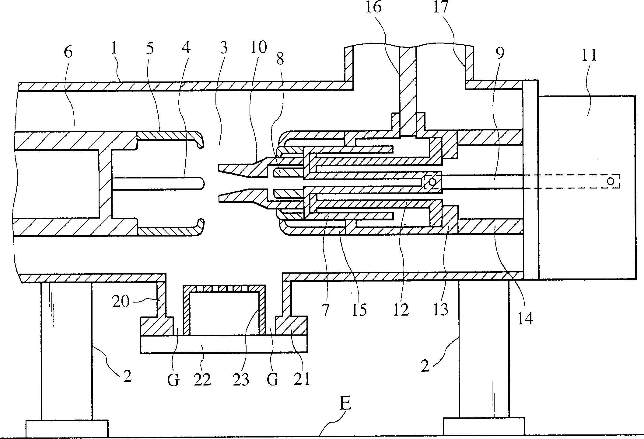
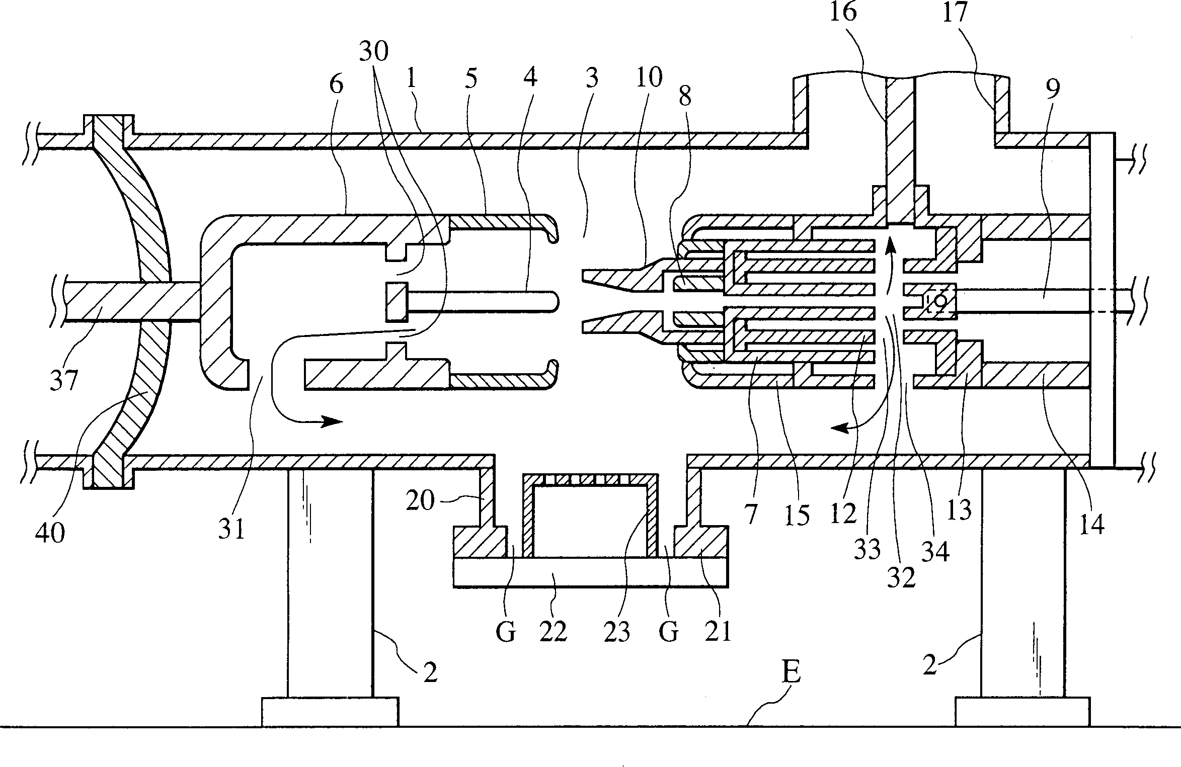
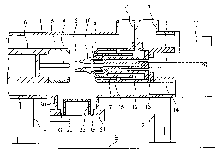
[0012] Referring to the gas insulated switchgear which is a gas blowing type gas blowing circuit breaker according to a preferred embodiment of the present invention figure 1 , the sealed container 1 containing the insulating gas is supported by the support member 2 on the foundation E or the device. The air blowing type air blowing circuit breaker 3 is installed in the sealed container 1 .

[0013] The air-blow type air-blown circuit breaker 3 has a static contact unit including a static contact 4 and a main static contact 5 surrounding the static contact 4 . The stationary contact 4 and the main stationary contact 5 are connected to the free end of the stationary conductor 6 . The stationary conductor 6 is electrically connected to a bus bar supported by an insulating support member not shown in the drawings.

[0014] The air blowing circuit breaker 3 has a movable contact unit including a movable contact 8 integrally formed with an air blowing cylinder 7 . An insulator l...


PUM


Abstract

A gas-insulated switchgear includes a sealed vessel filled with an insulating gas, a circuit breaker held in the sealed vessel, and a branch pipe attached to a lower part of the sealed vessel right below the circuit breaker. The branch pipe defines a hand hole for use in inspecting the circuit breaker, provides a place for installing an absorbent container and forms a foreign matter collecting space.

Description

technical field [0001] The present invention relates to a highly reliable gas-insulated switchgear, and more particularly to a gas-insulated switchgear suitable for use as a gas-blow type gas-blast circuit breaker. Background technique [0002] A general gas insulated switchgear has: a circuit breaker including a static contact and a moving contact; the circuit breaker is accommodated and filled with an insulating gas such as sulfur hexafluoride gas (SF 6 ) of the sealed container; the contact operating device placed outside the sealed container to operate the movable contact; the high-voltage conductor connected to the circuit breaker; the insulating partition connected to the circuit breaker; and the bus bar. [0003] During the assembly process of gas insulated switchgear or when the circuit breaker performs its function, impurities may be generated in the sealed container. If the impurities generated in the sealed container are conductive, the dielectric capacity of the...

Claims


Application Information

Patent Timeline
IPC IPC(8): H01H33/00H01H33/56
CPCH01H33/56H01H2033/888H01H33/00
Inventor 安藤智之木田顺三广濑诚小柳修
Owner HITACHI LTD
Why Eureka
Try Eureka