Assembled division wall system

A component and wall panel technology, which is applied in the field of combined partition wall system in the office, can solve the problems of complex construction, time-consuming, unfavorable environmental protection, etc., and achieve the effect of fast and accurate construction and installation, elegant office environment, and environmental protection

Inactive Publication Date: 2003-07-23
YAU LEE WAH CONCRETE PRECAST PROD SHENZHEN CO LTD
View PDF0 Cites 11 Cited by
  • Summary
  • Abstract
  • Description
  • Claims
  • Application Information

AI Technical Summary

Problems solved by technology

[0002] At present, the installation method of the office partition wall is relatively simple. Basically, the U-shaped cross-section profile rolled by steel plate is used as the keel. Most of the decorative panels are fixed on the keel by screws. Production and ins

Method used


Image

  • Assembled division wall system
  • Assembled division wall system
  • Assembled division wall system

Examples


Embodiment Construction

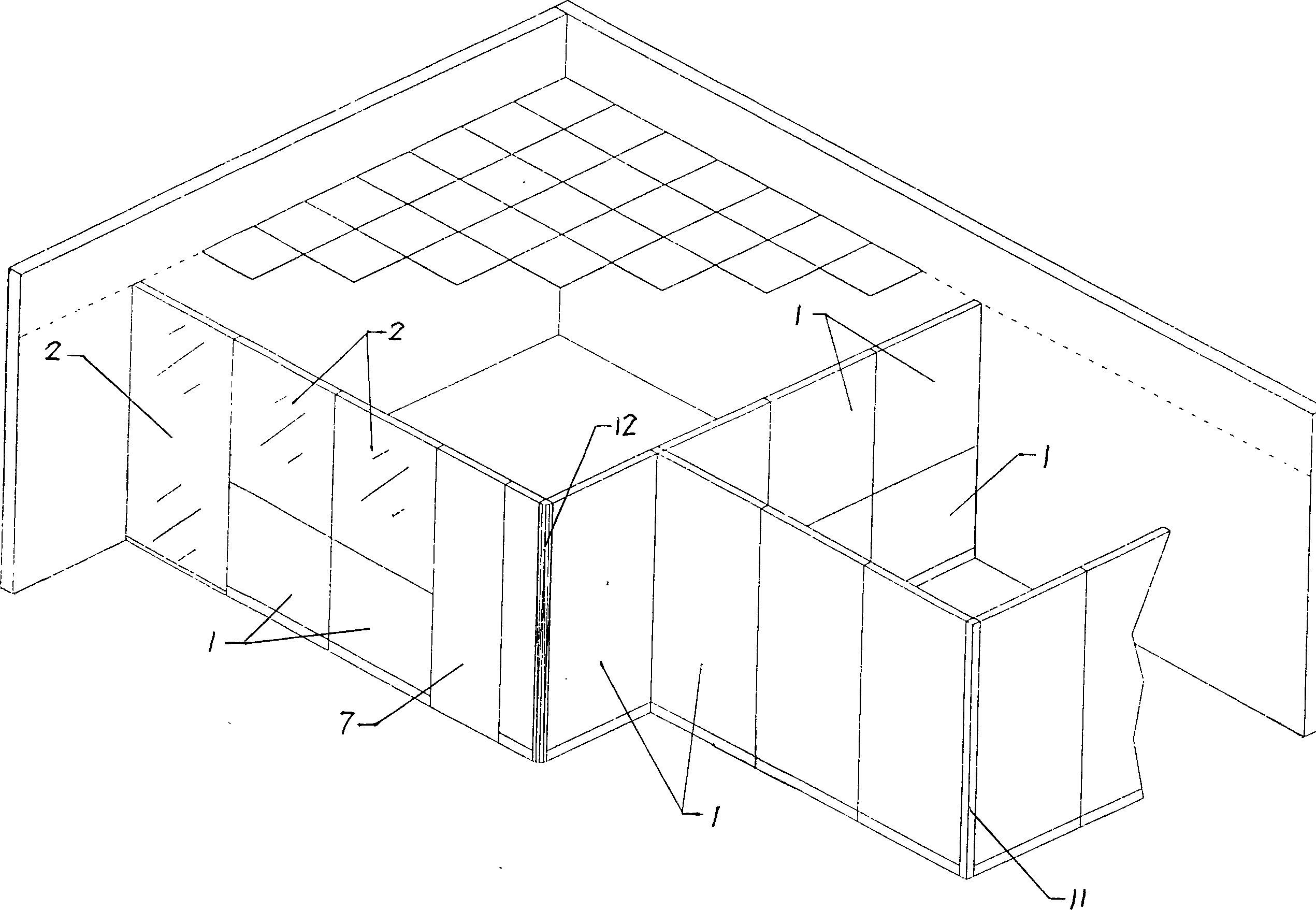
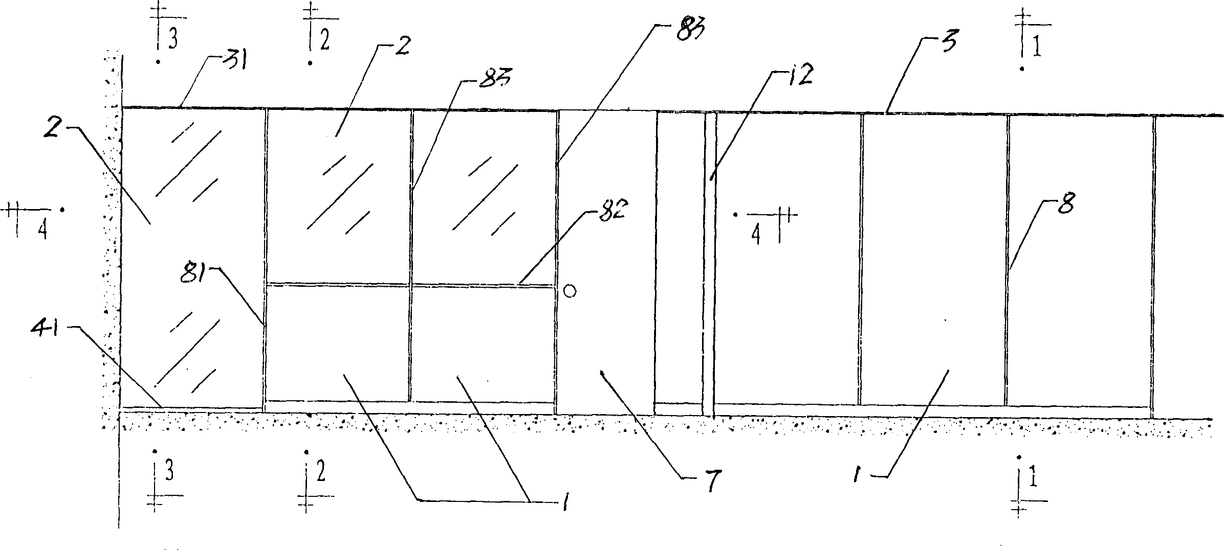
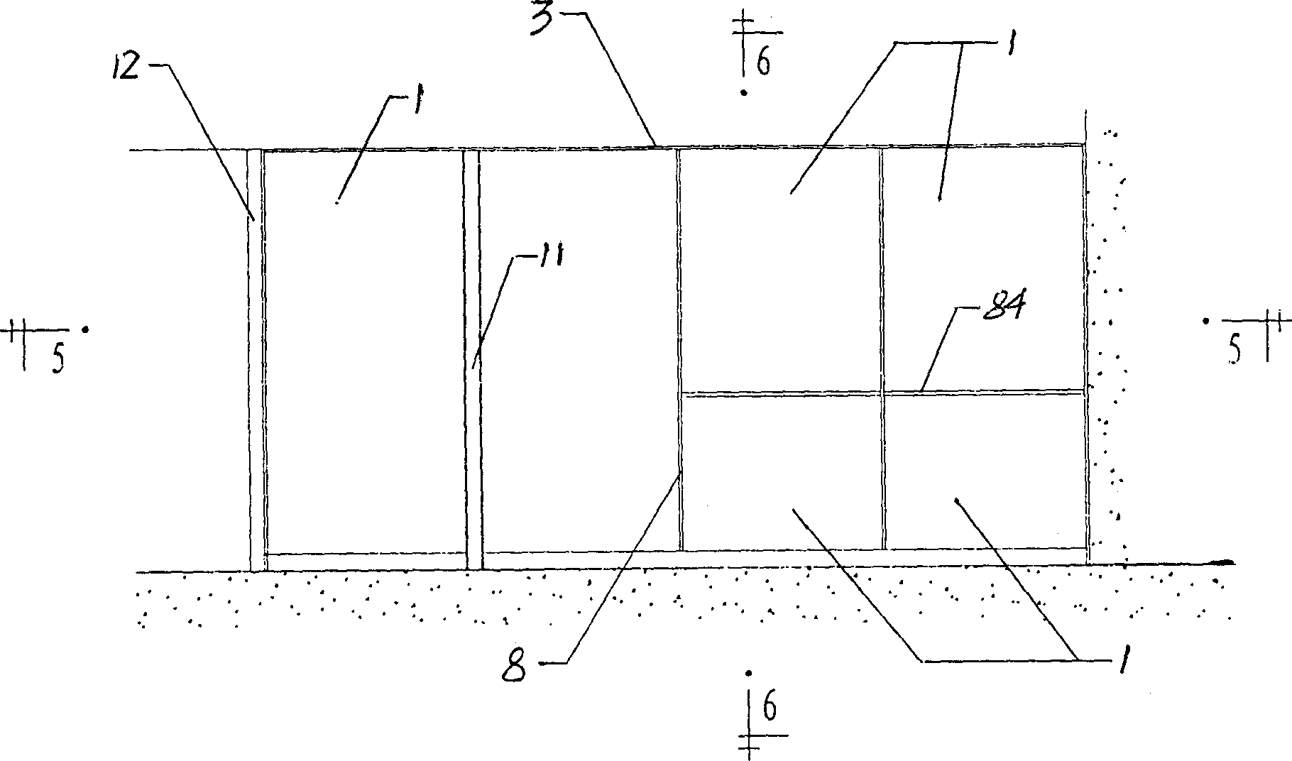
[0032] Such as figure 2 As shown, the combined partition wall system of the present invention includes a door 7, a partition wall composed of wall panels 1 or glass panels 2 for separating the interior space, a first keel assembly 3 for fixing the top edge of the wall panel 1 and the ceiling, and The sixth keel assembly 31 for fixedly connecting the top edge of the glass plate 2 to the ceiling, the second keel assembly 4 for fixedly connecting the bottom edge of the wall panel 1 to the ground, and the seventh keel assembly for fixedly connecting the bottom edge of the glass plate 2 to the ground Component 41, and the vertical for connecting the first or sixth keel component 3 or 31 fixed on the ceiling, the vertical edge of the partition wall, and the second or seventh keel component 4 or 41 fixed on the ground Keel components. The vertical keel assembly divides the partition wall into independent single blocks, and has different connecting members corresponding to different...


PUM


Abstract

A combined partion system is composed of door, the wall slab and glass plate for dividing space, vertical supporting main joist, slab connectors for connecting wall slabs to joist, glass connectors for fixing glass plate to joist, and U-shaped slots for connecting the wall slabs and glass plate to ceiling and floor. It is suitable for office room.

Description

technical field [0001] The invention relates to a building interior partition wall system, in particular to a combined partition wall system for offices. Background technique [0002] At present, the installation method of the office partition wall is relatively simple. Basically, the U-shaped cross-section profile rolled by steel plate is used as the keel. Most of the decorative panels are fixed on the keel by screws. Production and installation are complicated and time-consuming, cumbersome and unsightly, and when the position of the partition wall needs to be changed, the original partition wall must be destructively demolished and cannot be reused, which is not conducive to environmental protection. Contents of the invention [0003] The technical problem to be solved by the present invention is to provide a standardized combined partition wall system. [0004] The purpose of the present invention can be achieved by adopting the following technical measures, designing...

Claims


Application Information

Patent Timeline
IPC IPC(8): E04B2/74E04B2/82
Inventor 王志良易新亮
Owner YAU LEE WAH CONCRETE PRECAST PROD SHENZHEN CO LTD
Why Eureka
Try Eureka