Circular beating material feeding method in papermaking and device thereof

A circulating beating and feeding device technology, which is applied in pulp beating/refining methods, papermaking, textiles and papermaking, etc., can solve the problems of not meeting production requirements, uneven beating effect of pulp, affecting pulp beating performance, etc. , to achieve the effects of reducing retardation, reducing impact, improving papermaking performance and paper quality

Inactive Publication Date: 2003-08-06
SOUTH CHINA UNIV OF TECH
View PDF0 Cites 4 Cited by
  • Summary
  • Abstract
  • Description
  • Claims
  • Application Information

AI Technical Summary

Problems solved by technology

[0002] In the production practice of disc refiner circulation beating in the existing papermaking process, the quality of beating cannot meet the requirements of production because the slurry is beaten through one or more disc refiners; at this time, in order to improve the beating quality, often In the way of circular beating, the slurry is passed through the same or multiple disc refiners again or multiple times until the beating quality of the slurry meets the production requirements; in order to realize the circular beating, it is necessary to transfer the circulation in the existing pre-milling tower Slurry, the circulating slurry is directly sent into the pre-mill tower through the slurry pipe, and the slurry is concentrated in a solid column and falls at a certain point in the tower, resulting in a fast flow of the slurry at the drop point, while at other positions, especially in the tower Due to the friction between the slurry and the tower wall around the wall, the flow rate of the slurry is relatively slow. Therefore, the flow rate of the slurry at each position in the tower is different, and the front and rear slurry moves in a staggered manner, and cannot flow out of the circulation tower in a balanced and orderly manner. The beating effect of the pulp is uneven, which affects the beating performance of the pulp. This phenomenon is especially obvious for the medium-concentration pulp.

Method used


Image

  • Circular beating material feeding method in papermaking and device thereof
  • Circular beating material feeding method in papermaking and device thereof
  • Circular beating material feeding method in papermaking and device thereof

Examples


Embodiment 1

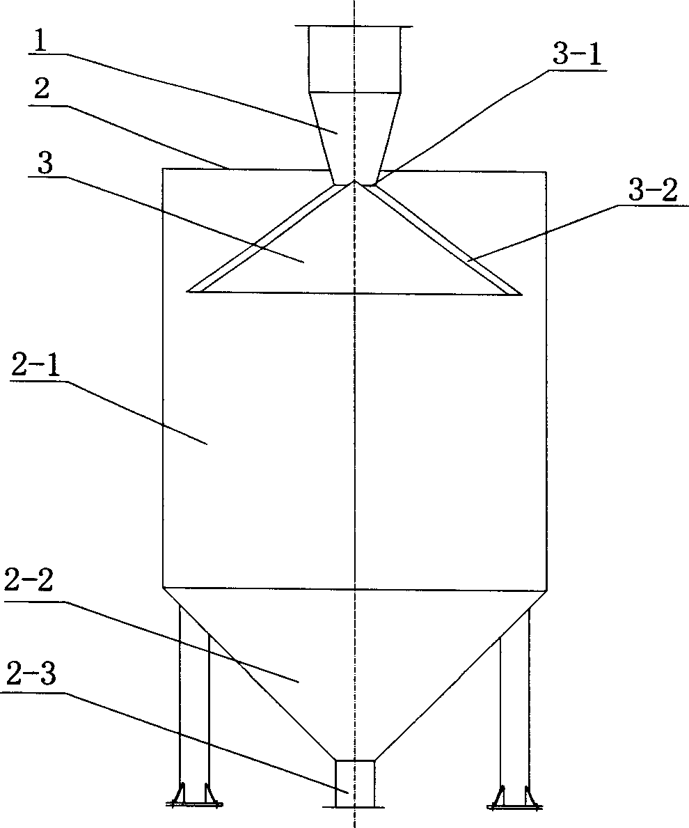
[0020] The specific structure of the present invention is as figure 1 shown by figure 1 It can be seen that this circulation beating and feeding device includes a slurry collection pipe 1, a circulation tower body 2, and a conical dispersion body 3. The upper ends are connected, and the circulation tower body 2 is composed of a cylindrical tower body 2-1 and a conical tower bottom 2-2. There is an outlet 2-3 at the tower bottom 2-2, and the conical dispersion 3 is located in the circulation tower body. The upper end is connected with the slurry collection pipe 1, and the conical dispersion body contains a conical flow channel 3-2, and the conical flow channel 3-2 communicates with the slurry collection pipe 1 through the opening 3-1.

[0021] The working principle of this device is: the circulating slurry falls into the conical dispersion 3 at the center through the slurry collection pipe 1, and the slurry is dispersed through the conical flow channel 3-2 in the conical dispe...

Embodiment 2

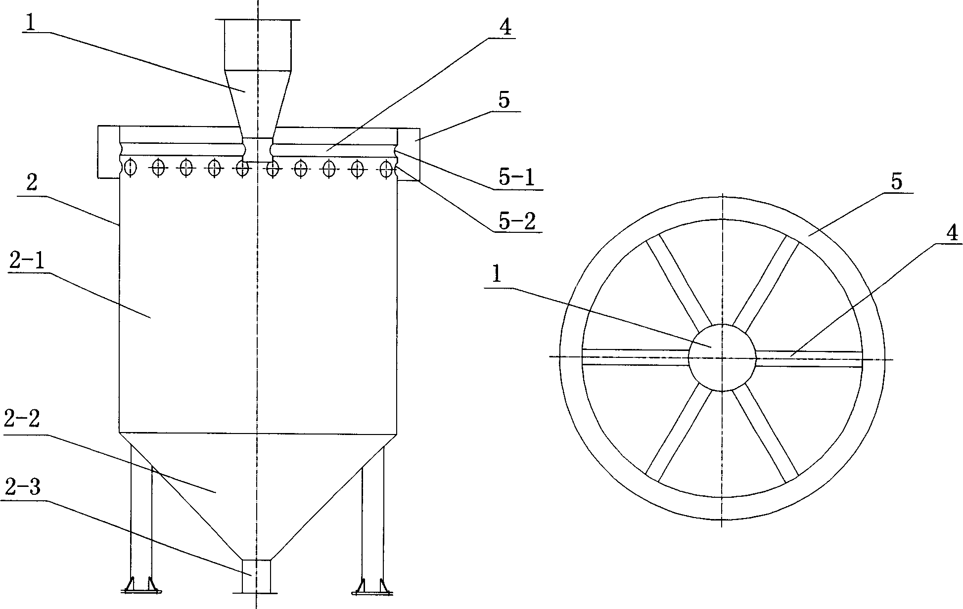
[0023] Another specific structure of the present invention is as figure 2 shown by figure 2 It can be seen that the circulation beating and feeding device includes a slurry collection pipe 1, a circulation tower body 2, a dispersion pipe 4, and a slurry tank 5. The slurry collection pipe 1 is a variable diameter pipe from large to small, and the circulation tower body 2 is composed of a The body 2-1 and the conical tower bottom 2-2 are formed, and an outlet 2-3 is opened at the tower bottom 2-2, and the dispersion pipe 4 is radially and symmetrically distributed around the slurry collecting pipe 1, and one end thereof is connected to the slurry collecting pipe. 1 is connected through a through hole, and the other end is connected with the slurry tank 5. The slurry tank 5 is located outside the upper end of the circulation tower body 2 and is connected to the dispersion pipe 4 and the circulation tower body 2 through the through holes 5-1 and 5-2 at the same time. connected....

Embodiment 3

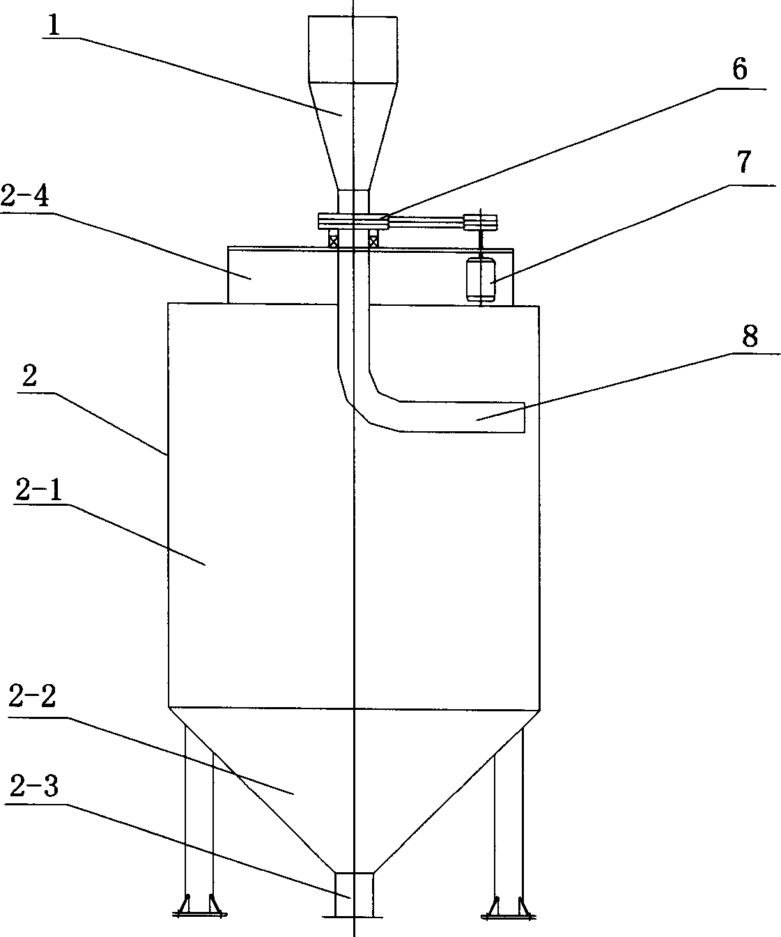
[0026] Another specific structure of the present invention is as image 3 shown by image 3 It can be seen that the circulation beating and feeding device includes a slurry collection pipe 1, a circulation tower body 2, a motor 7, a reducer 6, and a rotating dispersion pipe 8. The slurry collection pipe 1 is a variable diameter pipe from large to small, and the circulation tower body 2 Consists of a cylindrical tower body 2-1 and a conical tower bottom 2-2, an outlet 2-3 is opened at the tower bottom 2-2, a platform 2-4 is installed on the top of the tower, and a motor is installed on the platform 2-4 7. Reducer 6, one end of the rotating dispersing pipe 8 is connected to the slurry collecting pipe 1, and the other end is in the shape of an elbow, its opening is opposite to the inner wall of the circulation tower body 2, and the motor 7 is connected to the rotating dispersing pipe 8 through the reducer 6 .

[0027] The working principle of this device is: after the circulati...


PUM


Abstract

The circulating beating material feed method in the paper-making process includes circulating tower body pulp material collecting tube, and is characterized by that it also includes pulp material dispersion member which is respectively connected with circulating tower body and pulp material collecting tube, the described dispersion member can be made into the structure of conical flow passage, radiation dispersion flow passage and electric rotating dispersion tube. Said invention can change the centralized pulp fall into dispersed pulp fall along the tower wall, at the same time the impact offalling pulp to the pulp material in the tower can reduce the retardation action of tower wall on pulp material in the tower so as to make the pulp material in the tower stably fall downward and raise the beating quality, and improve paper-making property and paper quality.

Description

technical field [0001] The invention relates to a paper-making feeding technology, in particular to a method and a device for circulating beating and feeding during the paper-making process. Background technique [0002] In the production practice of disc refiner circulation beating in the existing papermaking process, the quality of beating cannot meet the requirements of production because the slurry is beaten through one or more disc refiners; at this time, in order to improve the beating quality, often In the way of circular beating, the slurry is passed through the same or multiple disc refiners again or multiple times until the beating quality of the slurry meets the production requirements; in order to realize the circular beating, it is necessary to transfer the circulation in the existing pre-milling tower Slurry, the circulating slurry is directly sent into the pre-mill tower through the slurry pipe, and the slurry is concentrated in a so...

Claims


Application Information

Patent Timeline
Patent Type & Authority Applications(China)
IPC IPC(8): D21D1/00
Inventor 朱小林李世扬曹国平余国藩雷利荣
Owner SOUTH CHINA UNIV OF TECH
Why Eureka
Try Eureka