Circular beating material feeding method in papermaking and device thereof
A circulating beating and feeding device technology, which is applied in pulp beating/refining methods, papermaking, textiles and papermaking, etc., can solve the problems of not meeting production requirements, uneven beating effect of pulp, affecting pulp beating performance, etc. , to achieve the effects of reducing retardation, reducing impact, improving papermaking performance and paper quality
- Summary
- Abstract
- Description
- Claims
- Application Information
AI Technical Summary
Problems solved by technology
Method used
Image
Examples
Embodiment 1
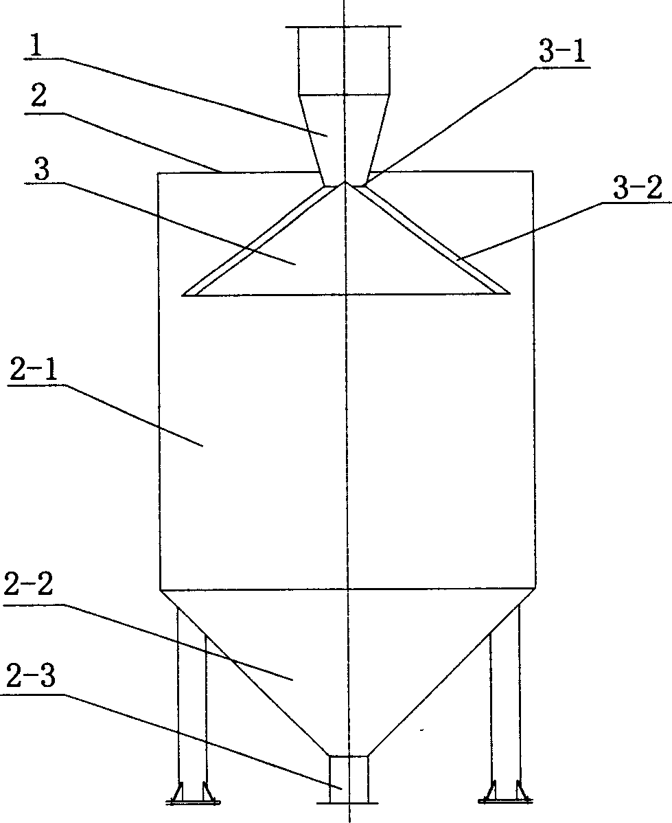
[0021] The specific structure of the present invention is as figure 1 shown by figure 1 It can be seen that this circulation beating and feeding device includes a slurry collection pipe 1, a circulation tower body 2, and a conical dispersion body 3. The upper ends are connected, and the circulation tower body 2 is composed of a cylindrical tower body 2-1 and a conical tower bottom 2-2. There is an outlet 2-3 at the tower bottom 2-2, and the conical dispersion 3 is located in the circulation tower body. The upper end is connected with the slurry collection pipe 1, and the conical dispersion body contains a conical flow channel 3-2, and the conical flow channel 3-2 communicates with the slurry collection pipe 1 through the opening 3-1.
[0022] The working principle of this device is: the circulating slurry falls into the conical dispersion 3 at the center through the slurry collection pipe 1, and the slurry is dispersed through the conical flow channel 3-2 in the conical dispe...
Embodiment 2
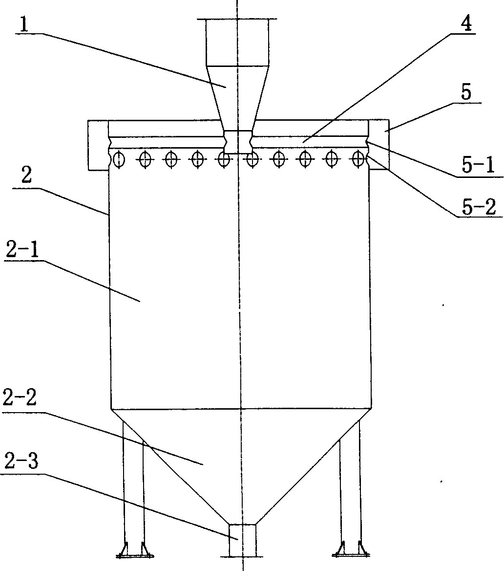
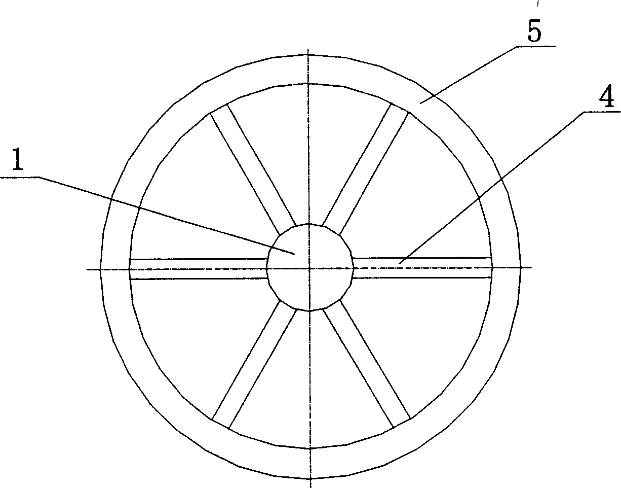
[0024] Another specific structure of the present invention is as figure 2 and image 3 shown by figure 2 and image 3 It can be seen that the circulation beating and feeding device includes a slurry collection pipe 1, a circulation tower body 2, a dispersion pipe 4, and a slurry tank 5. The slurry collection pipe 1 is a variable diameter pipe from large to small, and the circulation tower body 2 is composed of a The body 2-1 and the conical tower bottom 2-2 are formed, and an outlet 2-3 is opened at the tower bottom 2-2, and the dispersion pipe 4 is radially and symmetrically distributed around the slurry collecting pipe 1, and one end thereof is connected to the slurry collecting pipe. 1 is connected through a through hole, and the other end is connected with the slurry tank 5. The slurry tank 5 is located outside the upper end of the circulation tower body 2 and is connected to the dispersion pipe 4 and the circulation tower body 2 through the through holes 5-1 and 5-2 a...
Embodiment 3
[0027] Another specific structure of the present invention is as image 3 shown by image 3 It can be seen that the circulation beating and feeding device includes a slurry collection pipe 1, a circulation tower body 2, a motor 7, a reducer 6, and a rotating dispersion pipe 8. The slurry collection pipe 1 is a variable diameter pipe from large to small, and the circulation tower body 2 Consists of a cylindrical tower body 2-1 and a conical tower bottom 2-2, an outlet 2-3 is opened at the tower bottom 2-2, a platform 2-4 is installed on the top of the tower, and a motor is installed on the platform 2-4 7. Reducer 6, one end of the rotating dispersing pipe 8 is connected to the slurry collecting pipe 1, and the other end is in the shape of an elbow, its opening is opposite to the inner wall of the circulation tower body 2, and the motor 7 is connected to the rotating dispersing pipe 8 through the reducer 6 .
[0028] The working principle of this device is: after the circulati...
PUM
 Abstract
Description
Claims
Application Information
 - R&D
- Intellectual Property
- Life Sciences
- Materials
- Tech Scout
- Unparalleled Data Quality
- Higher Quality Content
- 60% Fewer Hallucinations
Browse by: Latest US Patents, China's latest patents, Technical Efficacy Thesaurus, Application Domain, Technology Topic, Popular Technical Reports.
© 2025 PatSnap. All rights reserved.Legal|Privacy policy|Modern Slavery Act Transparency Statement|Sitemap|About US| Contact US: help@patsnap.com


