Liquid crystal display and its fixed frame
A liquid crystal display, fixed frame technology, applied in the direction of static indicators, etc., can solve the problems of increasing mold cost, inconvenience, large volume, etc., and achieve the effect of reducing weight, cost, and cost
- Summary
- Abstract
- Description
- Claims
- Application Information
AI Technical Summary
Problems solved by technology
Method used
Image

Examples
no. 1 example
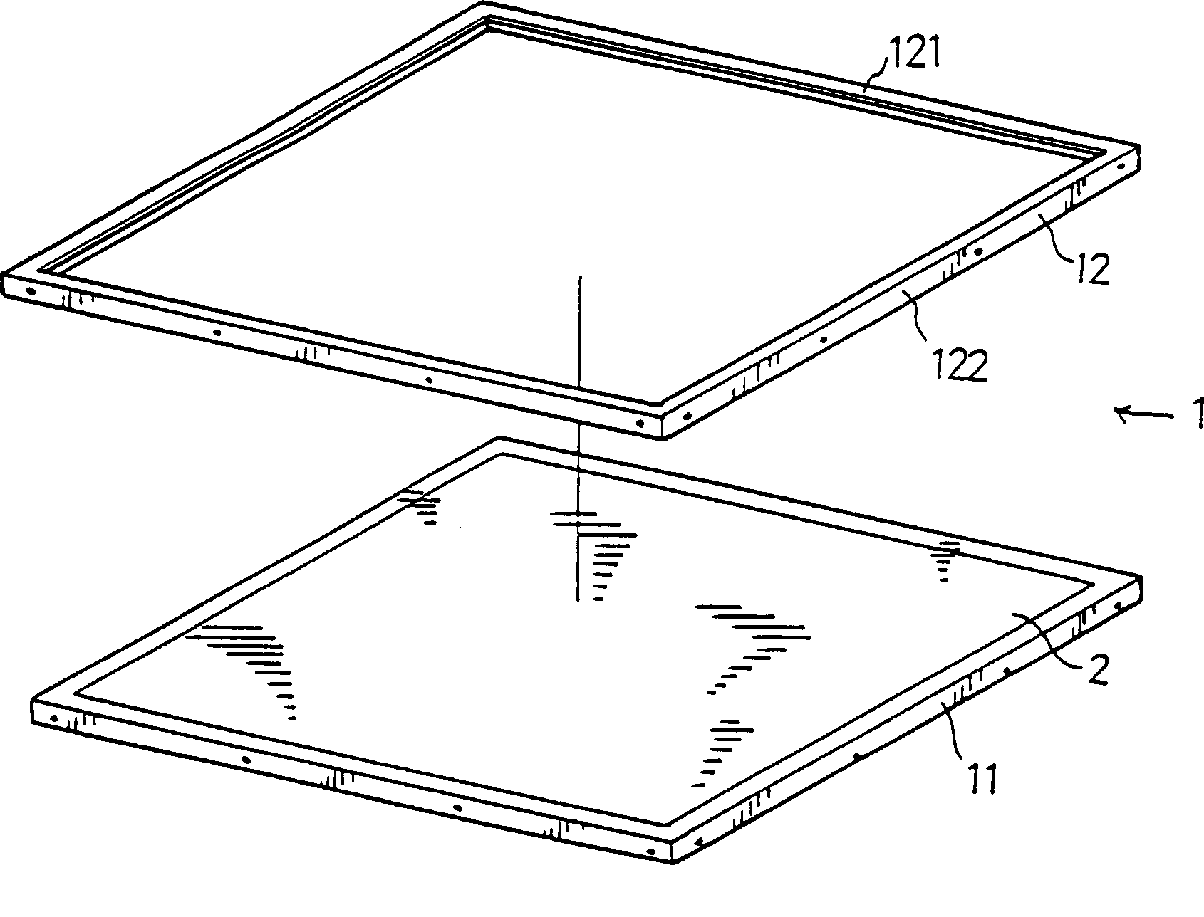
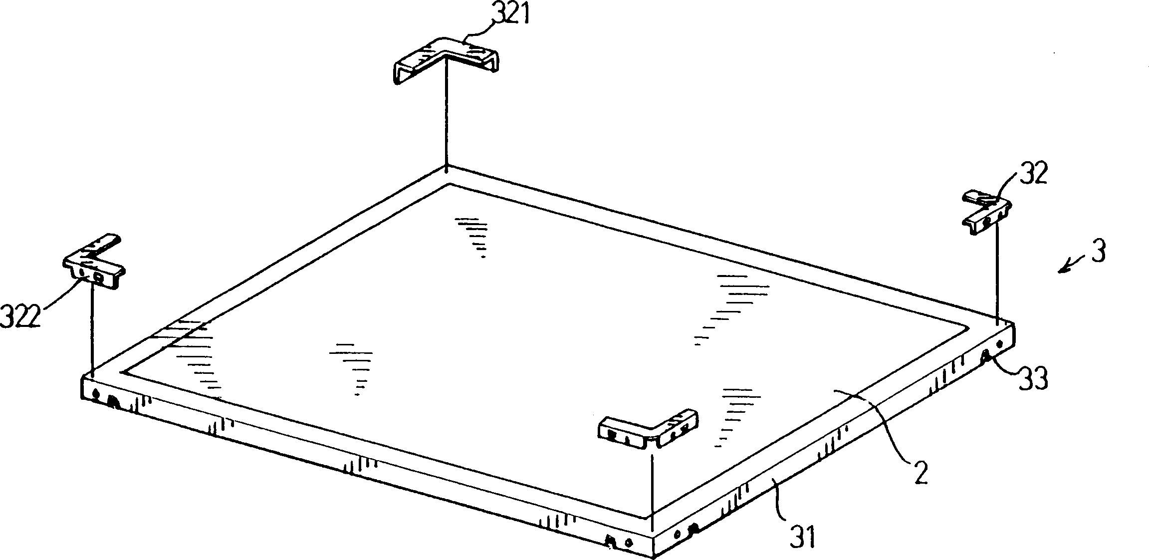
[0091] see figure 2The three-dimensional exploded schematic diagram of liquid crystal display fixed frame 3, this liquid crystal display comprises a panel module 2, and this panel module 2 is a rectangle, and has four sides and four corners; This fixed frame 3 comprises a mold frame 31, a plurality of The fixing piece 32 and a plurality of fixing structures 33 . The mold frame 31 is a concave and thick rectangle, and includes four corners and four frames, which are used to accommodate the panel module 2 and form the outer frame of the liquid crystal display. A frame of the mold frame can also be formed by the lamp module. (not shown) has only two corners and three frames instead; each fixing piece 32 includes a panel module fixing rib 321 and one side fixing portion 322, and the whole fixing piece 32 is combined with the mold frame 31 to fix the liquid crystal display wherein the panel module fixing rib 321 is used to press and fix the panel module 2, and coincides with part...
no. 2 example
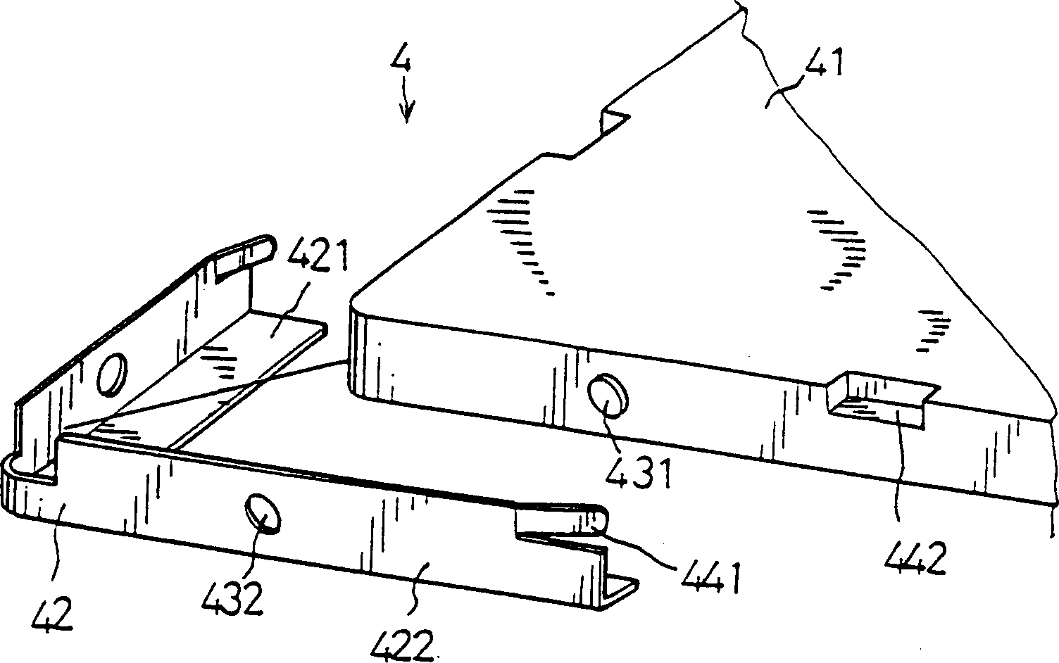
[0093] see Figure 3a and 3b A partial schematic diagram of the liquid crystal display fixed frame, the liquid crystal display is similar to the liquid crystal display of the first embodiment, including a panel module (not shown), the fixed frame 4 includes a mold frame 41, includes a panel module fixing rib 421 and a A plurality of fixing pieces 42 of the side fixing portion 422 and a plurality of fixing structures 43 , 44 .
[0094] The fixing structures 43 and 44 of this embodiment employ two different types of fixing structures in the same fixing frame 4 . Wherein the fixing structure 43 includes at least one positioning column 431 and a positioning hole 432, wherein the positioning column 431 is located on the mold frame 41, preferably located on the side of the mold frame 41, which protrudes outward from the plane of the mold frame, and the The positioning hole 432 is located on the fixing piece 42 , and the positioning hole 432 is located on the fixing piece 42 corres...
no. 3 example
[0097] see Figure 4a , a partial schematic view of the liquid crystal display fixed frame of 4b, the liquid crystal display is similar to the liquid crystal display of the first embodiment, including a panel module (not shown), a fixed frame 5 includes a mold frame 51, includes a panel module fixing rib 521 And a plurality of fixing pieces 52 of one fixing portion 522 , and a plurality of fixing structures 53 , 54 , wherein the fixing structure 53 is similar to the fixing structure 43 of the second embodiment, including at least one positioning post 531 and a positioning hole 532 .
[0098] This embodiment also includes a plurality of fixing structures 54, the fixing structure 54 is provided by a groove 541 located in the fixing piece 52, and the groove 541 is formed by the side fixing part 522, the panel module fixing rib 521 and a mold The frame fixing ribs 542 are defined and cover the sides of the mold frame 51, the panel modules (not shown) and the bottom of the mold fra...
PUM
 Abstract
Description
Claims
Application Information
 - R&D
- Intellectual Property
- Life Sciences
- Materials
- Tech Scout
- Unparalleled Data Quality
- Higher Quality Content
- 60% Fewer Hallucinations
Browse by: Latest US Patents, China's latest patents, Technical Efficacy Thesaurus, Application Domain, Technology Topic, Popular Technical Reports.
© 2025 PatSnap. All rights reserved.Legal|Privacy policy|Modern Slavery Act Transparency Statement|Sitemap|About US| Contact US: help@patsnap.com