Predictive method for surplus life, temperature testing structure and electronic device

An electronic device and life prediction technology, applied in the field of remaining life, can solve problems such as difficulties and achieve the effect of ensuring insulation performance

Inactive Publication Date: 2003-09-03
ORMON CORP
View PDF0 Cites 22 Cited by
  • Summary
  • Abstract
  • Description
  • Claims
  • Application Information

AI Technical Summary

Problems solved by technology

Therefore, it is more difficult to obtain the insulation of the electrolytic capacitor and the temperature sensor while correctly detecting the temperature of the electrolytic capacitor

Method used


Image

  • Predictive method for surplus life, temperature testing structure and electronic device
  • Predictive method for surplus life, temperature testing structure and electronic device
  • Predictive method for surplus life, temperature testing structure and electronic device

Examples


Embodiment Construction

[0061] Hereinafter, embodiments of the present invention will be described with reference to the drawings.

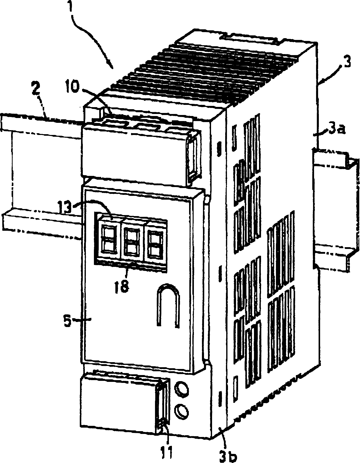
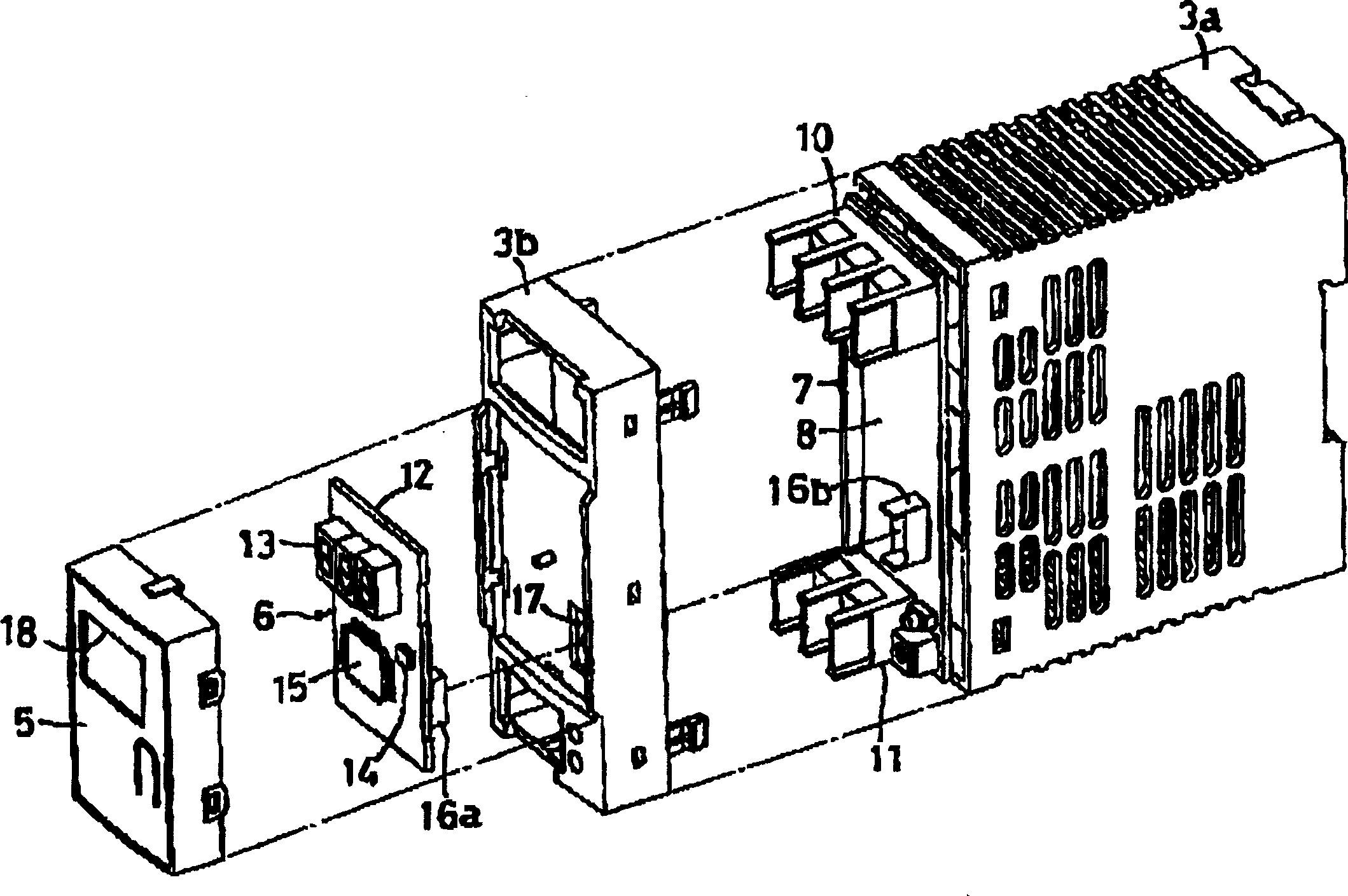
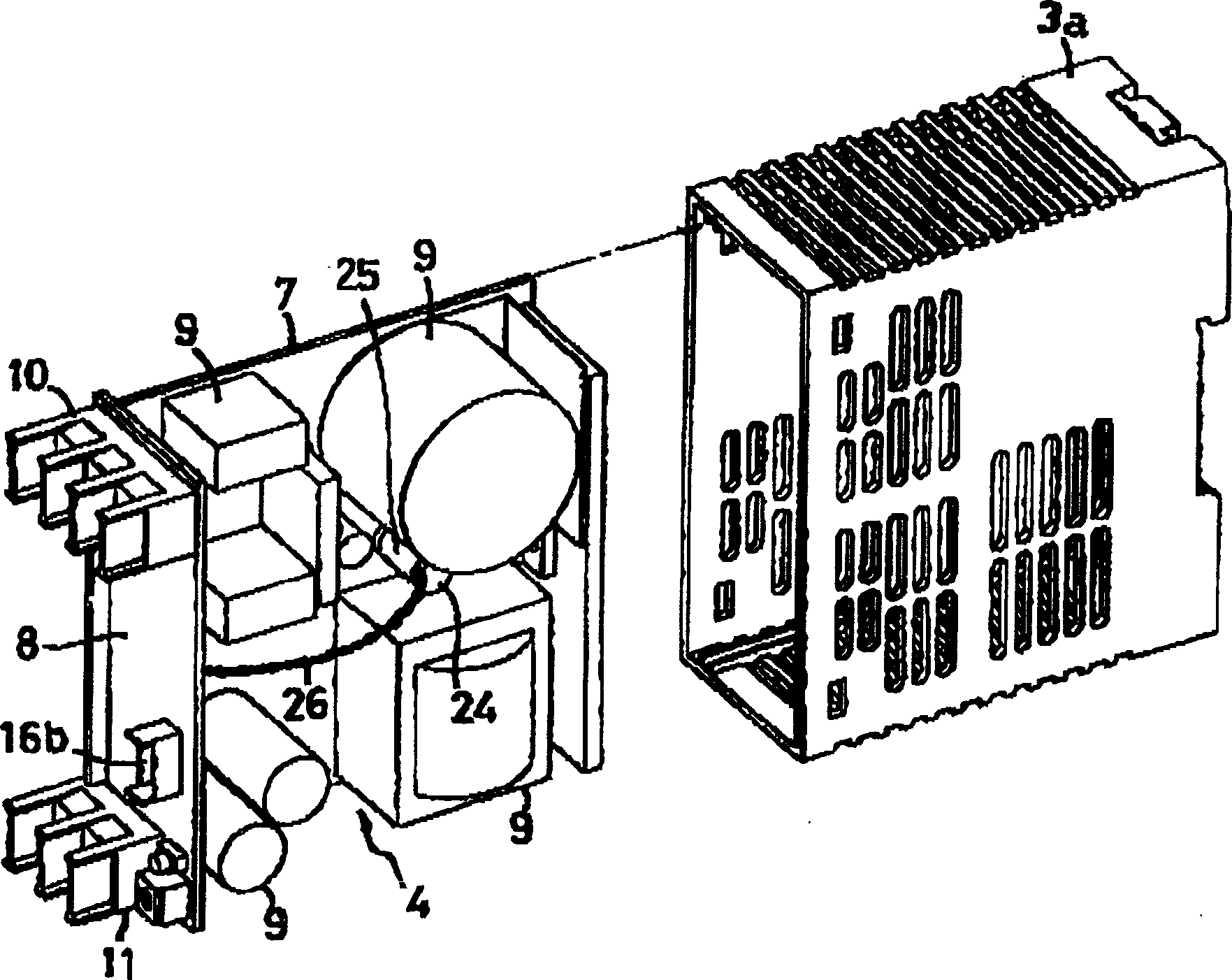
[0062] figure 1 An overall perspective view of a power supply unit 1 showing an example of an electronic device of the present invention, and figure 2 with image 3 Respectively represent the three-dimensional diagram of its decomposition, Figure 4 Indicates a partially sectioned plan view.

[0063] The power supply device 1 is configured as a box-shaped unit, and is detachably mounted on the front of a support rail 2 such as a DIN rail fixed to a power supply facility by a horizontal frame. A box-shaped housing body 3a and a resin front cover 3b fixedly connected to the front of the body are formed. Inside the box body 3, supports such as image 3 The power supply circuit section 4 shown.

[0064] In the front of the box body 3, that is, at the upper and lower middle parts of the front wall of the front cover 3b, a detachably fixed auxiliary housing 5 is formed ...


PUM

PropertyMeasurementUnit
thicknessaaaaaaaaaa

Abstract

The patent relates to a remaining lifetime estimating method, a temperature detection structure and an electronic equipment which ensures proper maintenance control without affecting a production process or the like by easily identify a residual service life. A temperature of an electrolytic capacitor 24 incorporated in equipment is detected, a remaining lifetime in actual use is calculated based on a temperature-lifetime law, and the remaining lifetime is indicated. A thin film tape 23 is wound around a temperature sensor 22 for insulation, and the electrolytic capacitor 24 and the temperature sensor 22 are accommodated in a heat-shrinkable tube 25, the secondary temperature sensor 22 is brought into tight contact with the primary electrolytic capacitor 24.

Description

technical field [0001] The present invention relates to a method of predicting the remaining life of a capacitor and the like, a temperature detection structure suitable for the method, and various electronic devices such as a power supply unit equipped with a capacitor. Background technique [0002] In such an electronic device, for example, in a power supply device, the life of an electrolytic capacitor having the shortest life among circuit components used therein is predicted as the life of the power supply device. [0003] As is well known, the life of an electrolytic capacitor can be calculated by the following calculation formula based on Arrhenius' law, which is a temperature-life law that expresses the relationship between temperature and life. [0004] Lx=Lo×2 (To-tx) / 10 ×k [0005] Lx: Estimated lifetime in actual use (hours) [0006] Lo: Guaranteed life at the highest operating temperature (hours) [0007] To: maximum operating temperature (°C) [0008] tx: ...

Claims


Application Information

Patent Timeline
Patent Type & Authority Applications(China)
IPC IPC(8): G01K3/04G01K7/00H01G9/00H01G13/00H02M3/28
CPCG01R31/028G01K3/04G01R31/003G01R31/64H02H6/00
Inventor 五十棲正志大场恒俊
Owner ORMON CORP
Why Eureka
Try Eureka