

Filling appliance
A technology for folders and folders, which is applied in the field of folders, and can solve problems such as high strength, uncomfortable movement of binding legs 103, and problems with operational reliability.
- Summary
- Abstract
- Description
- Claims
- Application Information
AI Technical Summary
Problems solved by technology
Method used
Image

Examples
Embodiment Construction
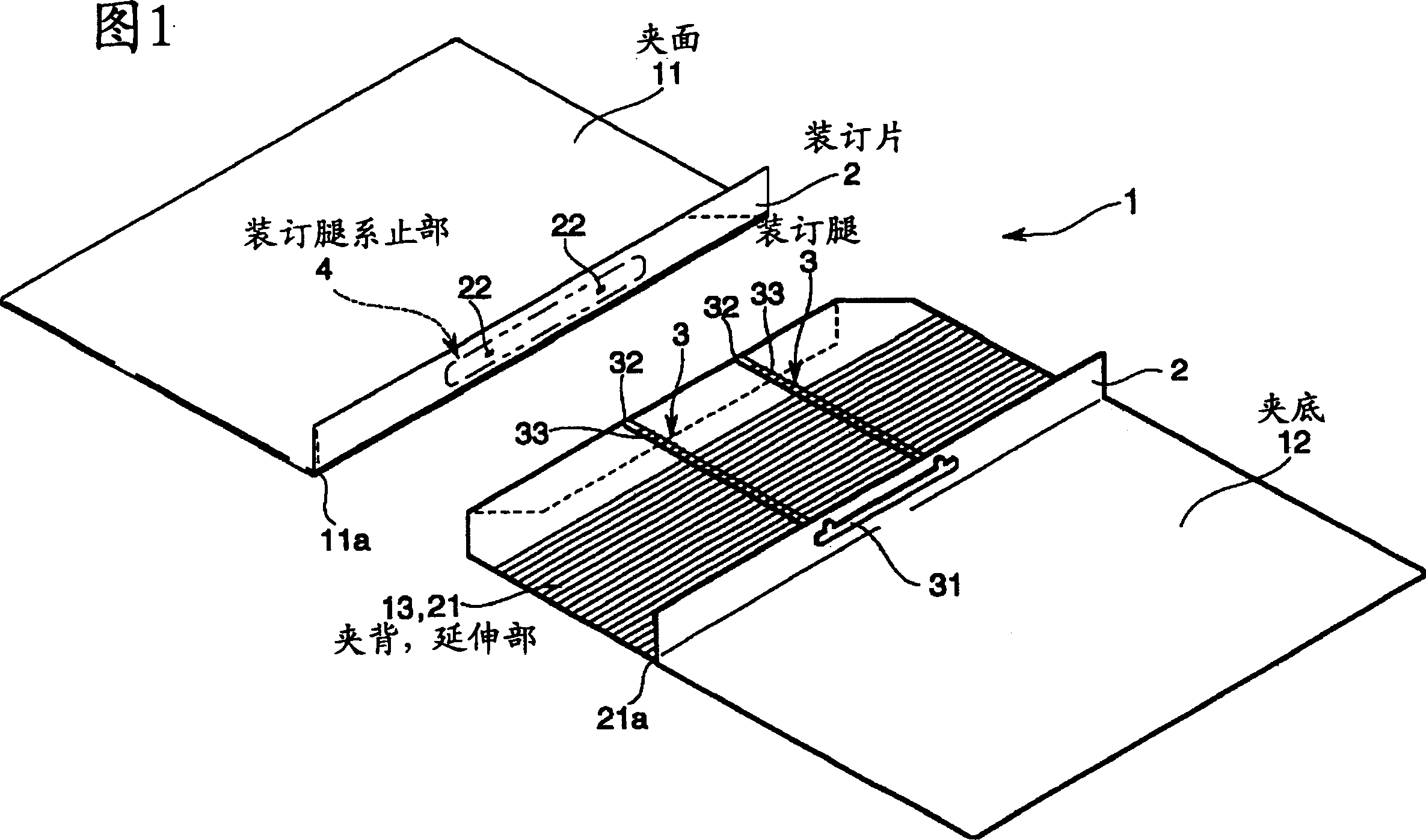
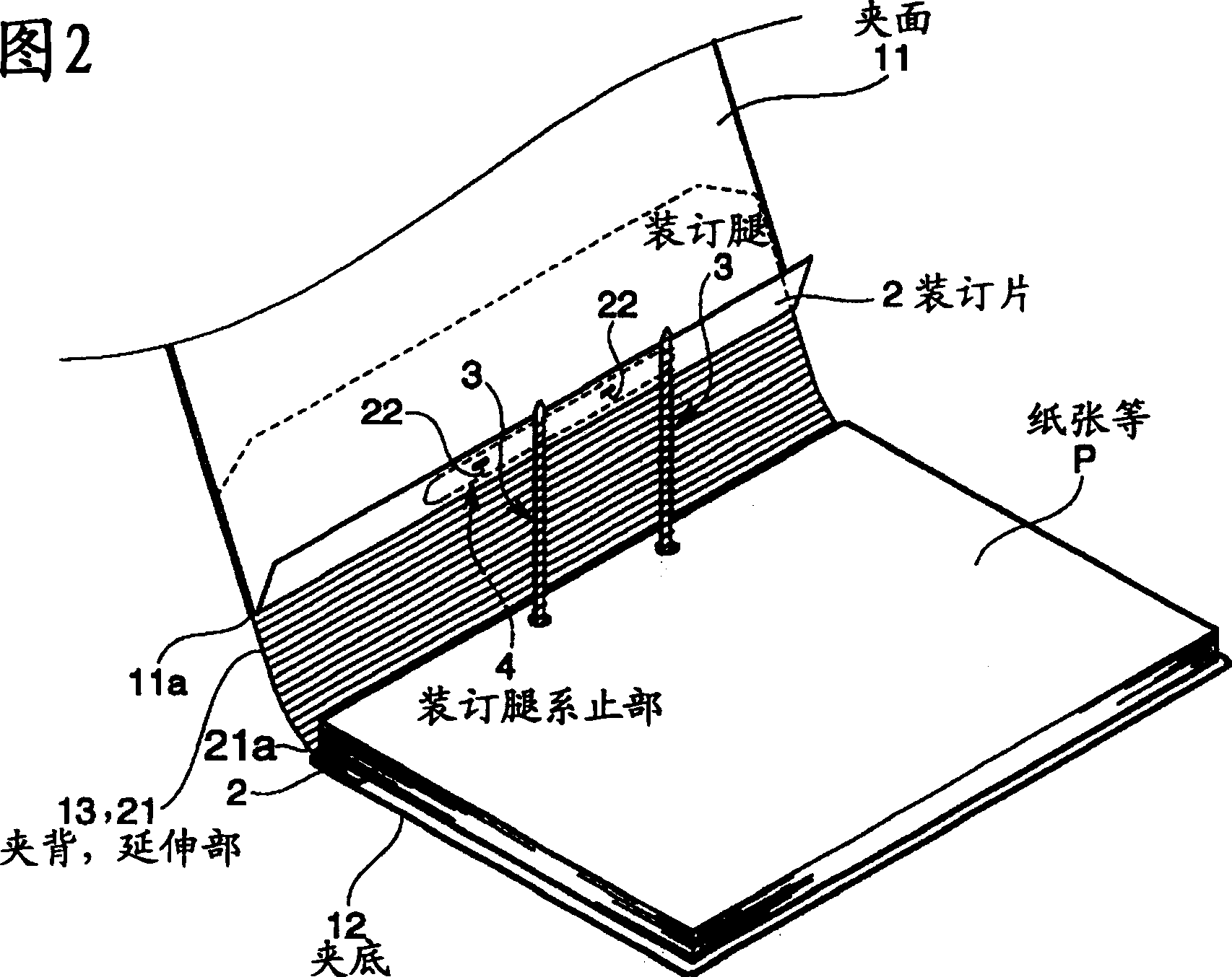
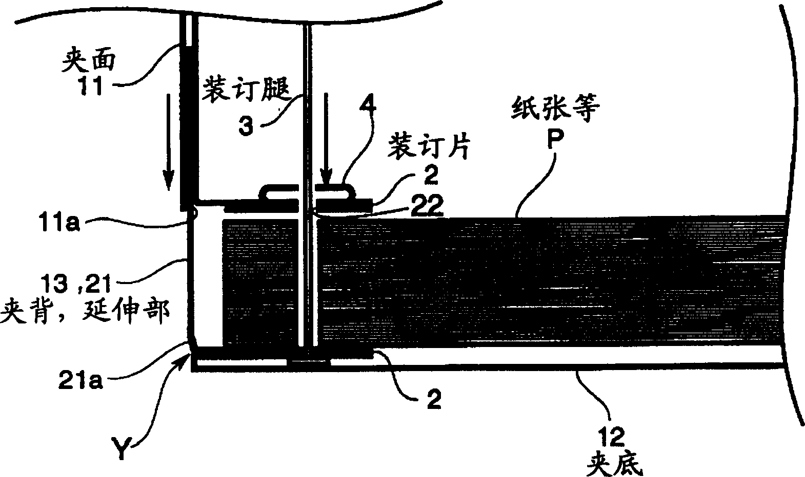
[0029] Below, refer to Figure 1- image 3 One embodiment of the present invention will be described.
[0030] The file folder of this embodiment, as shown in Figure 1 and Figure 2, has: the folder skin body 1 that is made of clamping surface 11, clamping bottom 12 and clamping back 13, is used for binding paper etc. P therebetween and is arranged on the aforementioned A pair of binding sheets 2 on the folder body 1, the base end 31 is supported on one binding sheet 2 and the front end side 32 penetrates through the binding leg 3 of the other binding sheet 2, so that the front end side 32 of the binding leg 3 continues to be inserted A binding leg fastening portion 4 fastens the binding leg 3 in a bent state in a part thereof and in the insertion portion.
[0031] One side binding piece 2 is formed on the position that is folded inwardly from the binding root side edge portion inner surface of the bottom 12 that constitutes the folder body 1, and the other side binding piece 2 ...
PUM
 Abstract
Description
Claims
Application Information