Flow measurement device
A flow measurement and switching device technology, which is applied in the direction of measuring devices, measuring flow/mass flow, liquid/fluid solid measurement, etc., can solve the problems of unguaranteed detection accuracy, tediousness, flow value error, etc.
- Summary
- Abstract
- Description
- Claims
- Application Information
AI Technical Summary
Problems solved by technology
Method used
Image

Examples
Embodiment 1
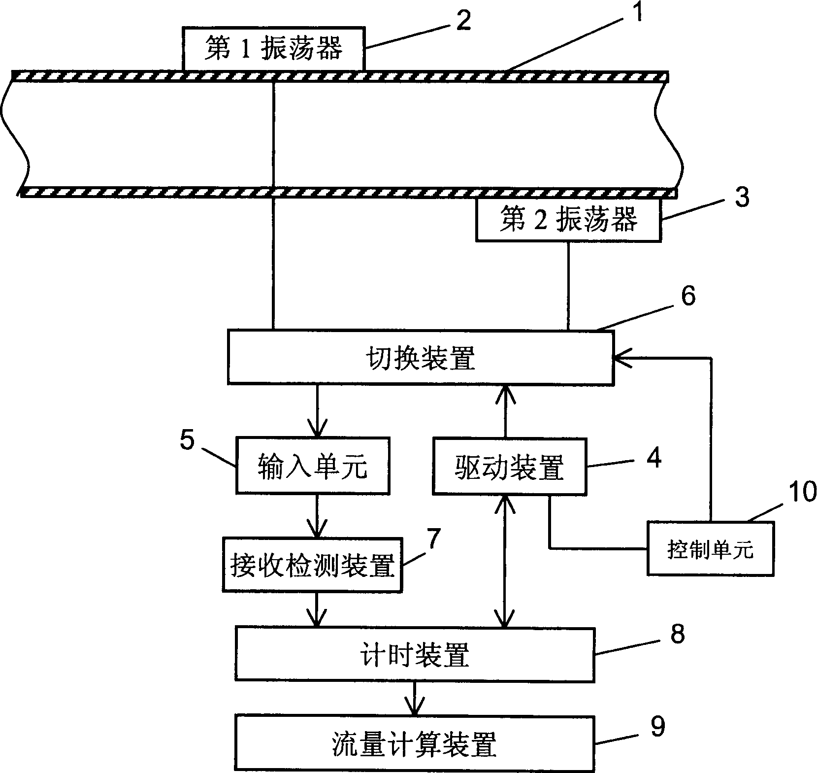
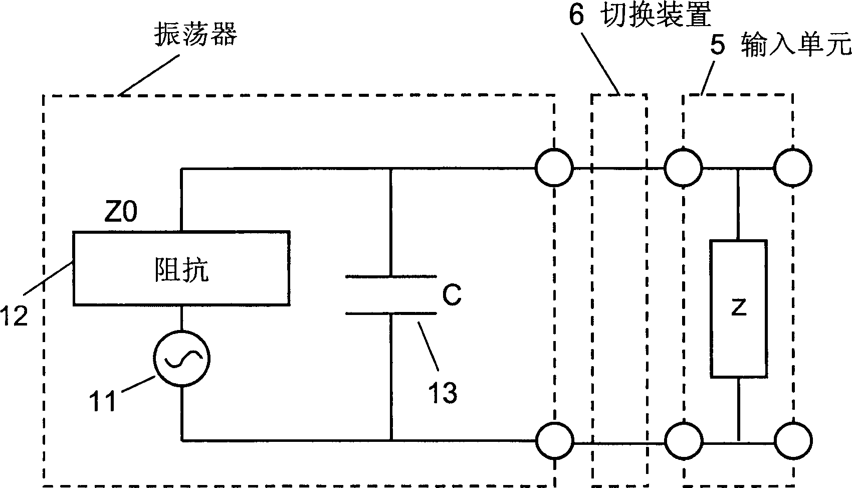
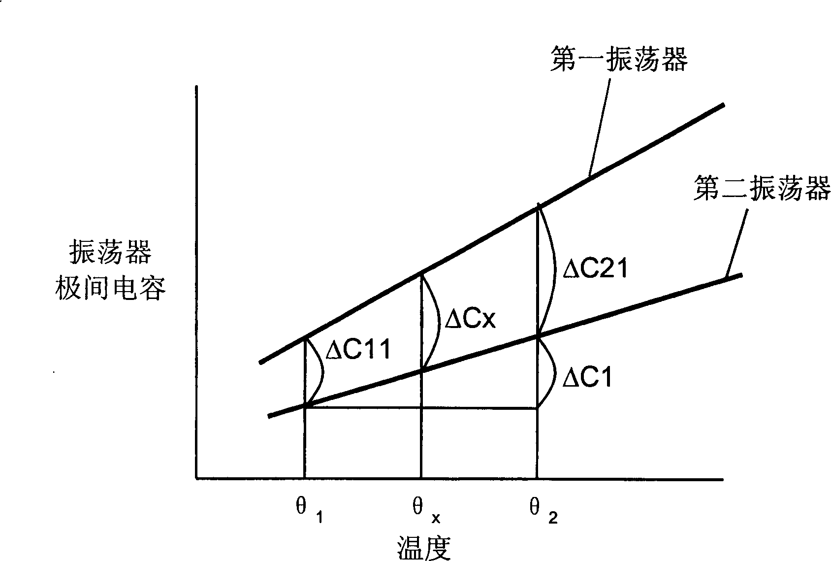
[0024] figure 1 It is a block diagram of the flow metering device in Embodiment 1 of the present invention. figure 2 It is an equivalent circuit diagram of the oscillator in the flow metering device in Example 1. image 3 It is a schematic diagram showing the temperature characteristics of the interelectrode capacitances of the first and second oscillators of the flow metering device in Example 1.
[0025] exist figure 1 , the measured fluid flows inside the fluid pipeline 1. The first oscillator and the second oscillator respectively transmit and receive ultrasonic signals. The vibrator is driven by the driving device 4 . The input unit 5 receives the output signals of the oscillators 2, 3 with low impedance. The switching device 6 is responsible for switching the connections between the oscillators 2 , 3 and the drive device 4 and the input unit 5 . The reception detection means 7 detects the reception time from the output signal of the input unit 5 and outputs it. ...
Embodiment 2
[0042] Figure 5 The flow metering device in Embodiment 2 of the present invention is shown in . for and figure 1 The components of the metering device in the shown embodiment 1 and the components with the same symbols are omitted in principle.
[0043] The repeating device 20 sends a repeating signal to the triggering device 21 after receiving the output signal from the comparing device 7 a of the receiving and detecting device 7 . The delay device 22 starts counting a predetermined delay time after receiving the output from the trigger device 21 .
[0044] The driving device 4 drives the oscillator through the switching device 6 after receiving the output of the trigger device 21 and the delay device 22 receiving the signal of the end of the delay time. The timer device 8 starts measuring the required time until receiving the ultrasonic reception signal of the receiver oscillator from the input unit 5 having low input impedance after receiving the detection start signal ...
PUM
 Abstract
Description
Claims
Application Information
 - R&D Engineer
- R&D Manager
- IP Professional
- Industry Leading Data Capabilities
- Powerful AI technology
- Patent DNA Extraction
Browse by: Latest US Patents, China's latest patents, Technical Efficacy Thesaurus, Application Domain, Technology Topic.
© 2024 PatSnap. All rights reserved.Legal|Privacy policy|Modern Slavery Act Transparency Statement|Sitemap