Colour kinescope device

A color picture tube and tubular electrode technology, applied in the field of electrodes, can solve problems such as poor reliability

Inactive Publication Date: 2003-10-01
PANASONIC CORP
View PDF3 Cites 2 Cited by
  • Summary
  • Abstract
  • Description
  • Claims
  • Application Information

AI Technical Summary

Problems solved by technology

Thus, when given these design constraints, reliability deteriorates

Method used


Image

  • Colour kinescope device
  • Colour kinescope device
  • Colour kinescope device

Examples


Embodiment 1

[0041] A color picture tube 1 according to an embodiment of the present invention will be described in detail below with reference to the accompanying drawings.

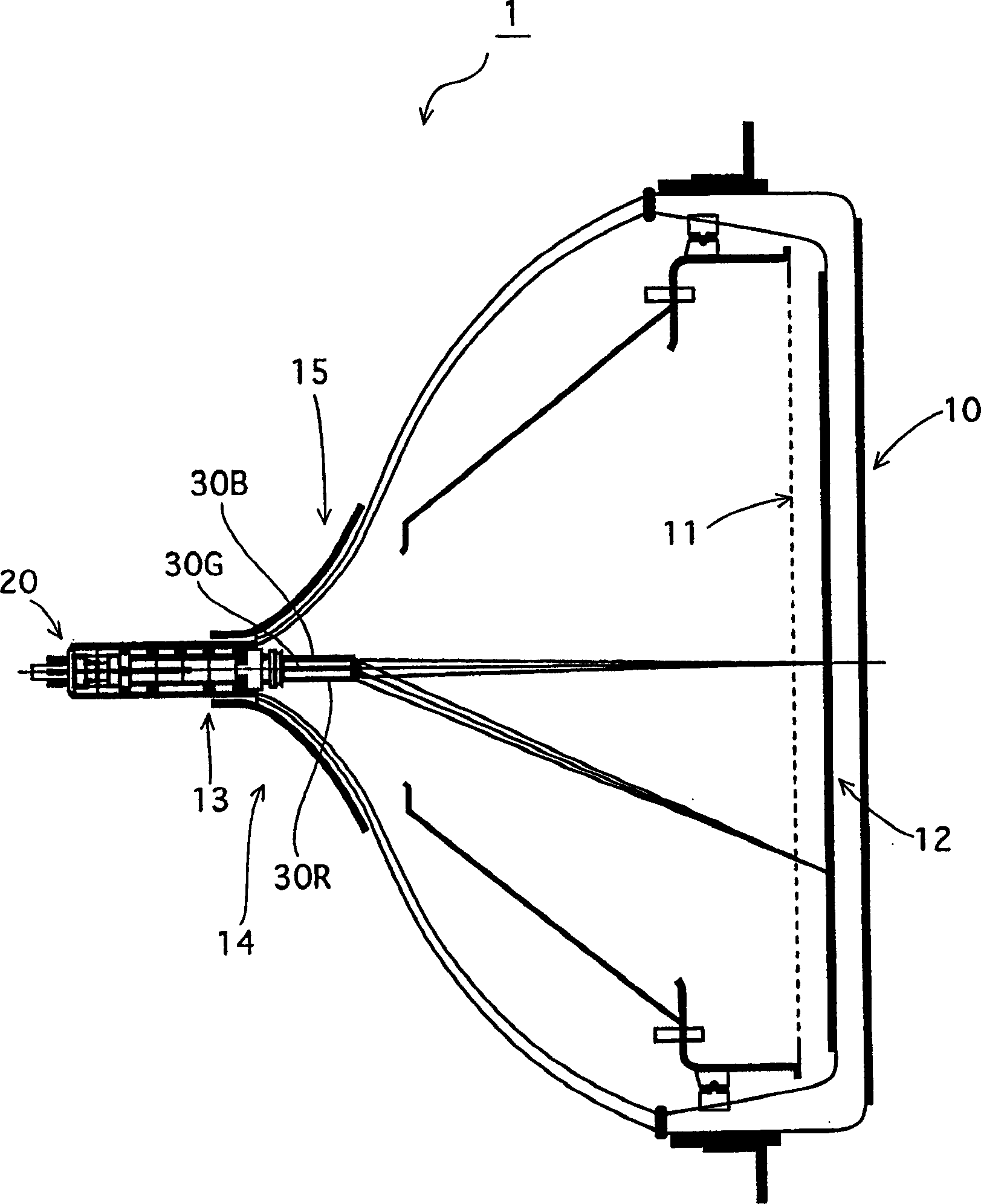
[0042] figure 1 is a cross-sectional view along the horizontal scanning direction, which shows the structure of the color picture tube 1 .

[0043]As shown in the figure, a color picture tube 1 is constituted by a picture tube 10 and a coaxial electron gun 20 . A picture tube 10 includes a screen 10 having R (red), G (green), B (blue) phosphors applied in a layered form on its inner side to face a shadow mask having a large number of The electron beams in it pass through the holes. The coaxial electron gun 20 is inserted from the base of the neck 13 of the kinescope 10 . Three electron beams 30R, 30G, 30B corresponding to RGB colors are emitted from the coaxial electron gun 20, and pass through the deflection magnetic field induced by the deflection yoke 15, which is along the widened portion 14 of the funnel and...

Embodiment 2

[0070] Embodiment 2 of the present invention will be described.

[0071] Figure 10 is a plan view showing the structure of the coaxial electron gun according to this embodiment, and Figure 11A with 11B The associated lens model is shown.

[0072] The difference from Embodiment 1 lies in that the ledge-shaped electrode plates 60 and 61 facing the space between the focusing electrode 27 and the final accelerating electrode 28 are provided on the field correcting electrode plate 27B. and project toward the space.

[0073] According to the structure, such as Figure 11A with 11B As shown, in addition to the lenses shown in FIG. 5 , quadrupole lenses 66, 67 and 68 are produced which have a greater divergence (concave lens) in the horizontal direction on the low pressure side than the main lens and a Greater focusing action than the main lens (convex lens).

[0074] Since these lenses allow the horizontal focusing effect to be weakened in the low pressure region, which is a...

Embodiment 3

[0077] Embodiment 3 of the present invention will be described.

[0078] Figure 12 is a plan view showing the structure of a coaxial electron gun according to Embodiment 3 of the present invention.

[0079] In the coaxial electron gun of this embodiment, a protrusion 29A is formed on the shield cover of the electron gun of Embodiment 1 so as to protrude into the final accelerating electrode, and a base 29B of the protrusion 29A serves as a field correcting electrode plate. As described above, the flange-shaped electrode plates 40 and 41 are provided on this base portion 29B.

[0080] In addition to the above actions / effects, according to this structure, when the shield cover is fitted with the final accelerating electrode, the field correcting electrode plate can be disposed inside the final accelerating electrode, and thus the assembly of the electron gun is facilitated.

[0081] Here, although Embodiments 2 and 3 are implemented independently, they may be implemented in c...


PUM


Abstract

A color picture tube device with a coaxial electron gun that makes it possible to avoid design difficulties by implementing a technique of applying a dynamic voltage to the OLF lens. The electrode plates in the shape of protrusions are attached to the field correcting electrode plates parallel to each other along the horizontal scanning direction. The field correcting electrode plates are horizontally long and flat plates in which three holes are provided. The shape of the plates is similar to that of the peripheral electrodes. hole. This structure allows the quadrupole lens to be formed by an auxiliary lens having a strong focusing effect in the horizontal direction and a diverging effect in the vertical direction, which can increase the HV difference. As a result, the dynamic voltage can be reduced without the design difficulties of the prior art, which does not have such a ledge-shaped electrode plate.

Description

technical field [0001] The present invention relates to a color picture tube device, and more particularly to an electrode configured as a main lens for focusing a plurality of electron beams on a screen. Background technique [0002] In general, a color picture tube has a capsule formed by a screen panel and a funnel connecting the panels, and displays color on a phosphor screen by emitting three electron beams from an electron gun provided in the neck of the funnel. Image, the formed screen faces the shadow mask on the inner surface of the panel while scanning horizontally and vertically, and the three electron beams are deflected by the horizontal and vertical deflection magnetic field by the The deflection coil produces. [0003] The magnetic field of the deflection yoke used in the above-mentioned color picture tube device generally has a self-converging structure to focus the three electron beams on the screen, and as a result the horizontal and vertical deflection ma...

Claims


Application Information

Patent Timeline
Patent Type & Authority Applications(China)
IPC IPC(8): H01J29/50H01J29/56
CPCH01J29/503H01J29/566H01J2229/5632H01J2229/5635H01J29/56
Inventor 助野雅彦上田康之
Owner PANASONIC CORP
Why Eureka
Try Eureka