Tightness spinning device of ring spinning frame

A technology of spinning frame and tensioning device, applied in spinning frame, continuous winding spinning frame, textile and paper making, etc., can solve the problems of poor evenness and influence of finished yarn

Inactive Publication Date: 2003-10-08
SHANGHAI TEXTILE MACHINERY CO LTD OF PACIFIC MECHATRONIC GRP
View PDF0 Cites 14 Cited by
  • Summary
  • Abstract
  • Description
  • Claims
  • Application Information

AI Technical Summary

Problems solved by technology

For this reason, the usual method is to install a collector in the drafting part, which can improv

Method used


Image

  • Tightness spinning device of ring spinning frame
  • Tightness spinning device of ring spinning frame
  • Tightness spinning device of ring spinning frame

Examples


Embodiment Construction

[0007] The present invention will be further described below in conjunction with accompanying drawing.

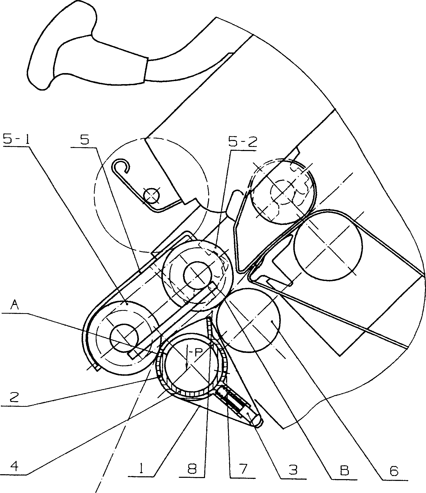
[0008] figure 1 It is a schematic diagram of the overall structure of the compact spinning device of the ring spinning frame. The device includes a breathable conveying ring 1, a condensation sleeve 2, a breathable conveying ring tensioning device 3, a suction pipe 4 with a suction port, and a pressurized transmission device 5. Under the combined effect of the negative pressure P passing through the air-permeable conveying ring 1 and the pressure top roller 5-1 of the pressure transmission device 5, the fiber bundle output by the front roller 6 is adsorbed on the surface driven by the pressure roller 5-1. On the surface of the air-permeable conveying ring 1, and along the direction of the coagulation groove 2-1 on the coagulation sleeve 2, it is in a state of tension, straightening and gathering, and then the fiber bundle is transported out of the holding point A with the m...


PUM


Abstract

A dense spinning unit for ring spinning frame is composed of drawing roller pair, roller seats, cradle pressing unit, air sucking tube with inlet and air oultet, condensing sleeve with condensing slot and sleeving on air sucking tube, stretching unit in the slide slot of condensing sleeve, air-permeable delivering ring sleeving on condensing slot and stretching unit, and drive pressing unit. Its advantages are high spinning power and high yarn quality.

Description

technical field [0001] The invention relates to a mechanical product used in the textile industry—a compact spinning device of a ring spinning frame. Background technique [0002] There are some shortcomings in the spinning mechanism of the traditional ring spinning frame, that is, after the drawn fiber bundle leaves the front roller with a certain width and in a free state, it is immediately processed into yarn. The region forms the spinning triangle area. Since the loose fibers in the spinning triangle area cannot be well controlled, many fibers on the periphery of the fiber bundle will be lost in advance or cannot be completely controlled, resulting in many fibers not being twisted into the yarn. Protruding out of the yarn to form "hairiness". At the same time, due to the unequal tension of the fibers in the spinning triangle during the twisting process, when the yarn is subjected to tension, the strength of the yarn is lower than the sum of the bearing capacity of the f...

Claims


Application Information

Patent Timeline
IPC IPC(8): D01H1/02D01H5/66D01H5/70
Inventor 汪倚君胡洪才
Owner SHANGHAI TEXTILE MACHINERY CO LTD OF PACIFIC MECHATRONIC GRP
Why Eureka
Try Eureka