Ophthalmologic apparatus

An equipment and ophthalmology technology, applied in the fields of eye testing equipment, ophthalmoscope, medical science, etc., can solve problems such as discomfort, poor operability of inspectors, and disorganized appearance, and achieve the effect of avoiding bending or damage.

Inactive Publication Date: 2003-10-15
KK TOPCON
View PDF0 Cites 9 Cited by
  • Summary
  • Abstract
  • Description
  • Claims
  • Application Information

AI Technical Summary

Problems solved by technology

[0006] Therefore, when using an imaging device that involves a cable connection in the viewing system, when the examiner attempts to change the position of the device relative to the eye to be examined by turning the viewing system horizontally, the cables in the exposure channel will collide with the viewing system. contact, resulting in poor operability for inspectors
[0007] In addition, the exposed cables under the palate support table may come into contact with the examinee's knees, etc., causing them to be disturbed and uncomfortable.
[0008] Also, since the cable channel is exposed, the slit lamp microscope as a whole looks a bit haphazard in appearance

Method used


Image

  • Ophthalmologic apparatus
  • Ophthalmologic apparatus
  • Ophthalmologic apparatus

Examples


Embodiment Construction

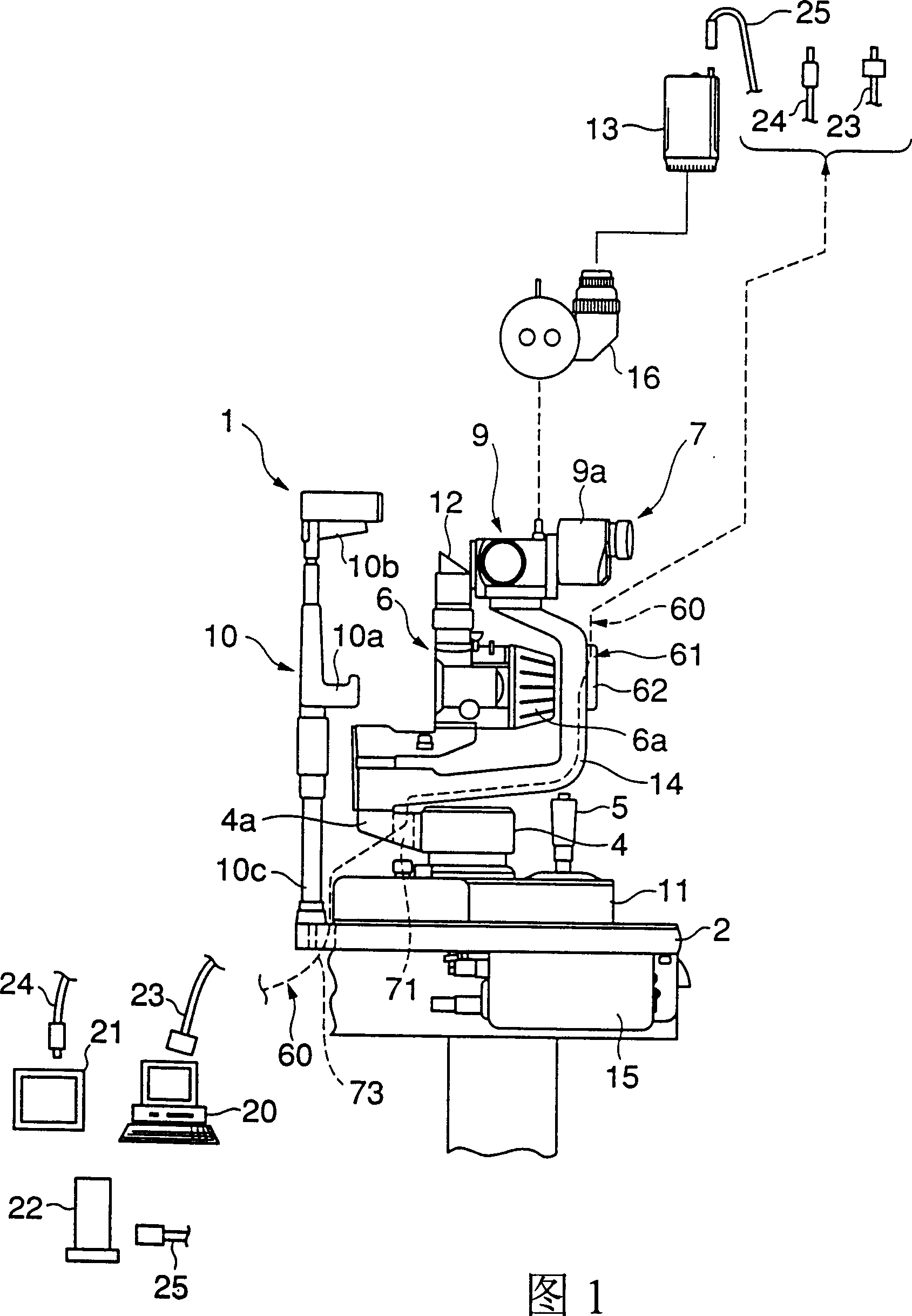
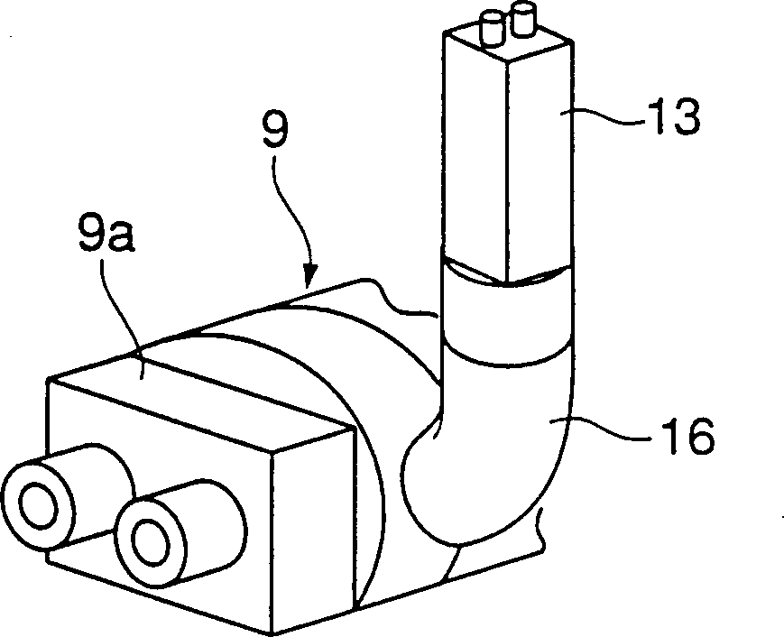
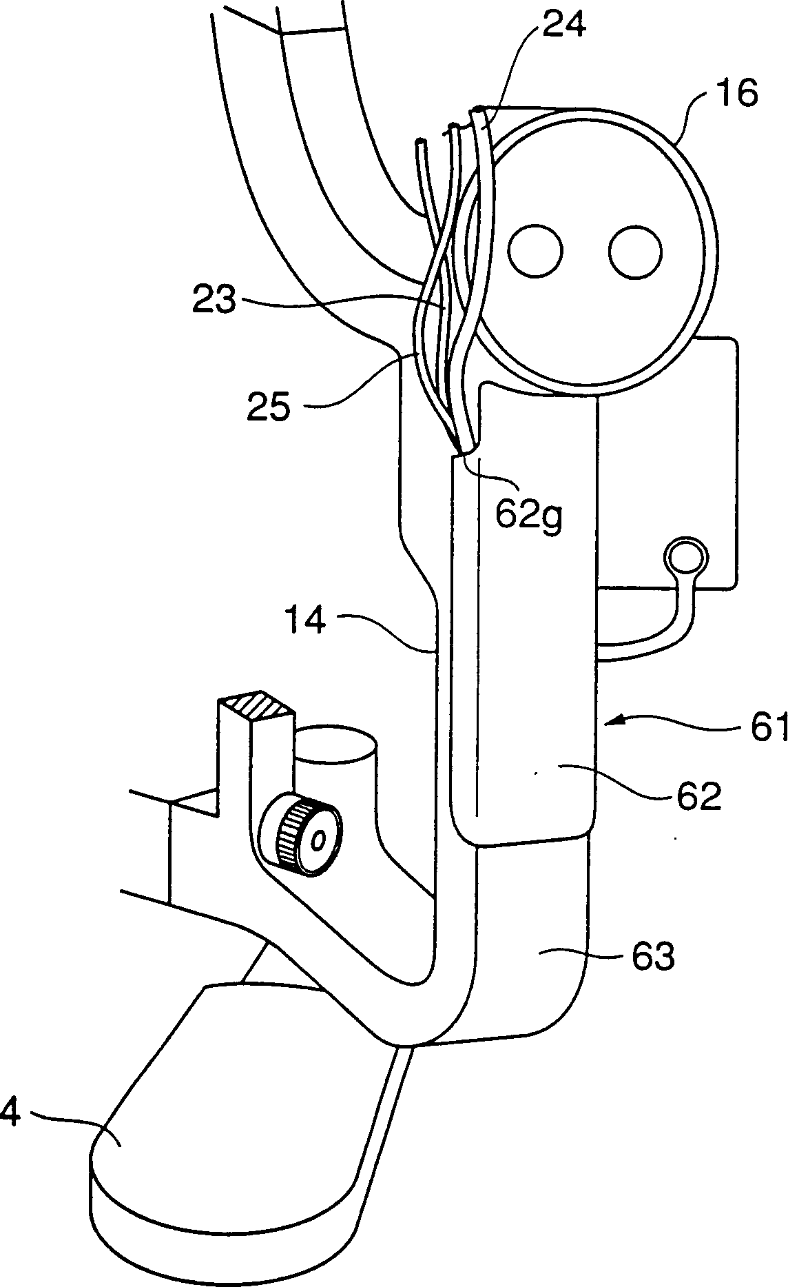
[0044]An embodiment of the present invention will be described below. The slit lamp microscope 1 shown in FIG. 1 constitutes the ophthalmic apparatus according to this embodiment. The equipment is equipped with a base 11 supported on the ophthalmoscope table 2, which can be horizontally moved horizontally and vertically through the movement mechanism part 3; a base 4 supported on the base 11 in the vertical direction; An operating handle 5 for horizontally moving the base horizontally and vertically by tilting operation; a light source portion 6a supported so as to be horizontally rotated by a protruding bush 4a of the base 4; an illumination system 6 having a prism 12 and the like An observation system 7 for observing the eye E to be inspected and a palate support table 10 having a palate of the examinee opposite to the main cylindrical body 9 for accommodating the observation system 7 objective lens The stand 10a, the front holder 10b, and the base portion 10c installed on ...


PUM


Abstract

Disclosed is an ophthalmologic apparatus, such as a slit lamp microscope, which is improved in terms of cable routing when an imaging apparatus is used, thereby achieving an improvement in operability for the examiner, mitigating the bother or discomfort for the subject, and realizing an improved outward appearance. In a slit lamp microscope using cables for electrical connection between an imaging apparatus and an image processing system or a control system, there is provided a cable hole having an opening provided with at least two curved corners through which cables connected to the imaging apparatus come together and which is formed so as to enclose partially the near portion of the protrusive axle shell of the base, or there is provided a cable routing path in which the cables connected to the imaging apparatus are routed by way of an accommodating groove with a detachable cover provided on the front side of the support arm, a cable hole provided in a protrusive axle shell of a base protruding toward a chin rest stand from a pedestal, a cable hole of the chin rest stand, and a cable hole provided in a table, to be passed under the table.

Description

technical field [0001] The present invention relates to an ophthalmic device, such as a slit lamp microscope. Background technique [0002] The slit lamp microscope has long been used as an ophthalmic device for ophthalmic use. [0003] In slit-lamp microscopy, the slit illuminator, or slit lamp and background illumination for illuminating the entire eye being examined, is projected onto the eye being examined from an illumination system supported on a pedestal mounted on a table Above, the position of the eye is fixed by placing the palate of the examinee on the palate supporting platform erected at one end of the platform, and the slit image of the eye (such as the cornea) is observed by an observation optical system supported on the base. cross-sectional image) by means of a support arm that can be rotated horizontally, and by using imaging equipment such as a video camera installed on the observation optical system to collect slit images and overall images of the eye, u...

Claims


Application Information

Patent Timeline
Patent Type & Authority Applications(China)
IPC IPC(8): A61B3/00A61B3/12A61B3/135A61B3/14
CPCA61B3/0033A61B3/145A61B3/135
Inventor 武田孝纪大野正喜阿部知好小山年洋
Owner KK TOPCON
Why Eureka
Try Eureka