Synchronous lifting control method of bottom sections for lying furniture such as bed

A technology of synchronous lifting and control method, which is applied to the ambulance of vehicles, beds, hospital beds, etc. It can solve the problems of complicated and troublesome operation, singleness, and difficulty in the optimal lifting state of the bottom part of the knee.

Inactive Publication Date: 2003-10-22
PARAMOUNT BED CO LTD
View PDF1 Cites 2 Cited by
  • Summary
  • Abstract
  • Description
  • Claims
  • Application Information

AI Technical Summary

Problems solved by technology

This operation is very complicated and troublesome, and the operator must also adapt to it
Also, it can be difficult to frequently reproduce optimal lifts for the bottom part of the back and the bottom part of the knees
[0015] b. In the above method b, due to the use of the interconnected structure, the lifting state of the bottom part of the back and the bottom part of the knees realized in an interconnected manner will inevitably be single, and it is impossible to change it. It is also difficult to effectively prevent the body from sliding and at the same time, for example Discomfort such as pressure

Method used


Image

  • Synchronous lifting control method of bottom sections for lying furniture such as bed
  • Synchronous lifting control method of bottom sections for lying furniture such as bed
  • Synchronous lifting control method of bottom sections for lying furniture such as bed

Examples


Embodiment Construction

[0035] Preferred embodiments of the present invention are described in detail below in conjunction with the accompanying drawings.

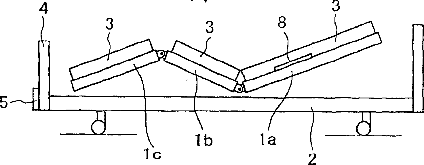
[0036] figure 1 It is a side view showing an embodiment of the whole bed to which the control method of the synchronous lift bottom part of the present invention is applied. The bed shown consists of a back bottom part 1a for raising the back part of the bed-rider, a knee-bottom part 1b for raising the bed-rider's knees, and a leg bottom part 1c corresponding to the bed-rider's legs. The above-mentioned back bottom portion 1a, knee bottom portion 1b and leg bottom portion 1c are connected to each other so as to form a bendable bottom corresponding to the whole body, and are supported by the bed frame 2 . In addition, mattresses 3 are provided for the above-mentioned back bottom portion 1a, knee bottom portion 1b, and leg bottom portion 1c, respectively. The mattresses 3 are shown separated from each other, but it is also possible to use an inte...


PUM


Abstract

A method of controlling the coordinative raising of support portions of a base support for a bed or the like, the base support having a back-support portion (1a) for raising the back of a subject lying thereon and a leg-support portion (1b) for raising the knees of a subject lying thereon, in which the respective support portions are provided with respective lifting mechanisms, characterised in that a pressure detecting means (8) is interposed between the back-support portion (1a) and the back of the subject, wherein where the back-support portion (1a) is pivotally rotated and raised to an inclined position, the leg-support portion (1b) is also raised, wherein the leg-support portion (1b) is controlled to lower when the pressure applied from the back-support portion (1a) to the back of the subject and detected by said pressure detecting means (8) has increased to a preset value.

Description

technical field [0001] The present invention generally relates to a control method for the simultaneous lifting of the bottom part of a lying appliance such as a bed (hospital bed, intensive care unit bed (ICU bed), long term care bed, etc.) or a stretcher. In more detail, the present invention relates to the simultaneous raising of a lower back portion for raising the back position of a recliner and a lower portion for raising the knees of a reclining appliance on a lying appliance having a lower back portion and a lower knee portion. Part of the bottom part of the knee, so as to achieve the following purpose of the synchronous lift control method. Background technique [0002] Some lying appliances such as beds or stretchers are provided with a back bottom part for raising the back of the occupant and a knee bottom part for elevating the occupant's knees, and these two parts can be separated by separate parts. Lift the mechanism to lift. [0003] Such reclining appliance...

Claims


Application Information

Patent Timeline
Patent Type & Authority Applications(China)
IPC IPC(8): A47C20/04A47C20/08A61G7/00A61G7/015A61G7/018
CPCA47C20/041A47C20/08A61G7/018A61G7/015A61G2203/42A47C21/00
Inventor 长冈浩堀谷正男井上晓
Owner PARAMOUNT BED CO LTD
Why Eureka
Try Eureka