Elevator hoist and elevator device

A hoist and elevator technology, which is applied in the direction of hoisting devices, elevators in buildings, transportation and packaging, etc., and can solve problems such as time-consuming and labor-intensive

Inactive Publication Date: 2003-10-22
MITSUBISHI ELECTRIC CORP
View PDF0 Cites 10 Cited by
  • Summary
  • Abstract
  • Description
  • Claims
  • Application Information

AI Technical Summary

Problems solved by technology

[0019] In addition, these adjustment operations are usually repeated alternately by the inspection of parallelism or clearance and the reassembly of the relatively heavy brake coil 3 to meet the requirements, which is a time-consuming and labor-intensive ope

Method used


Image

  • Elevator hoist and elevator device
  • Elevator hoist and elevator device
  • Elevator hoist and elevator device

Examples


Embodiment Construction

[0037] Embodiments of the present invention will be described below using the drawings.

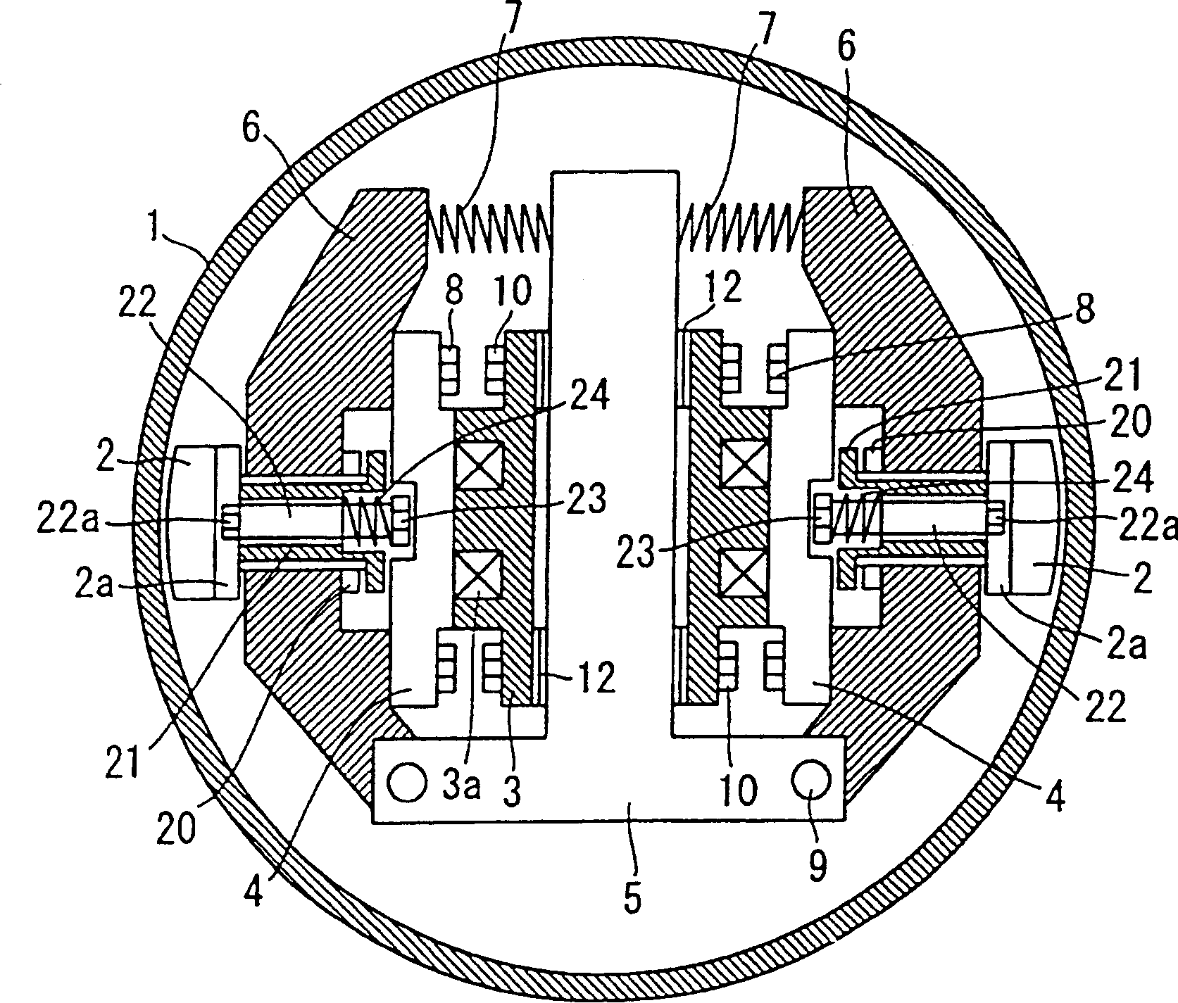
[0038] figure 1 It is a cross-sectional view showing the outline of an elevator hoist according to a first embodiment of the present invention.

[0039] As shown in the figure, a braking part is placed inside the brake drum 1 that is thrust and rotates around the main shaft not shown in the figure. The braking part is mainly composed of: a lining 2, a braking coil 3, an armature 4, and a coil The fixed part 5, the arm 6, the compression spring 7, and the washer 12 constitute.

[0040] In detail, the coil fixing part 5 is fixed at the central part of the brake drum 1 . The coil fixing part 5 is sandwiched, and the lining 2, the brake coil 3, the armature 4, the arm 6, the compression spring 7, the spacer 12 and other components are respectively arranged on both sides. Then, on both sides of the coil fixing part 5 , the brake coil 3 is screwed and connected by the bolt 10 by means of th...


PUM


Abstract

An elevator hoist, wherein mechanisms for adjusting a gap between linings formed so as to come into contact with and separate from a brake drum and the brake drum when the linings are separated from the brake drum are installed in an arms for supporting the linings, whereby the adjustment of the gap between the linings and the brake drum can be performed easily in a short time.

Description

technical field [0001] The invention relates to an elevator hoist and elevator device that drives a traction rope to lift a car and a counterweight, in particular to an elevator hoist and an elevator device with a braking part near a brake drum. Background technique [0002] In the conventional elevator hoist, the brake part for braking the brake drum is placed in the brake drum. [0003] Below, use Image 6 A conventional elevator hoist will be described. Image 6 It is a schematic cross-sectional view of a conventional elevator hoist. [0004] In the figure, a braking part is placed inside the brake drum 1 which receives thrust and rotates around a main shaft not shown in the figure. The braking part mainly consists of a lining 2, a braking coil 3, an armature 4, and a coil fixing part. 5, arm 6, compression spring 7, spacer 12 constitute. [0005] In detail, the coil fixing part 5 is fixed at the central part of the brake drum 1 . The coil fixing part 5 is sandwiched, ...

Claims


Application Information

Patent Timeline
IPC IPC(8): B66B11/08B66D5/08
CPCB66D5/30B66D5/08B66B11/08
Inventor 冈田浩二丸山直之汤村敬
Owner MITSUBISHI ELECTRIC CORP
Why Eureka
Try Eureka