Ink-jet recording head
An inkjet recording and ink technology, which is applied in the field of inkjet recording heads, can solve the problems of increased loss, increased ink droplets, and reduced energy efficiency.
- Summary
- Abstract
- Description
- Claims
- Application Information
AI Technical Summary
Problems solved by technology
Method used
Image
Examples
reference example 1
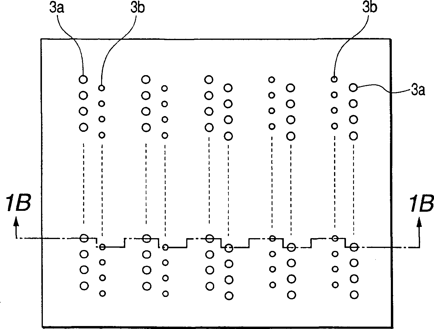
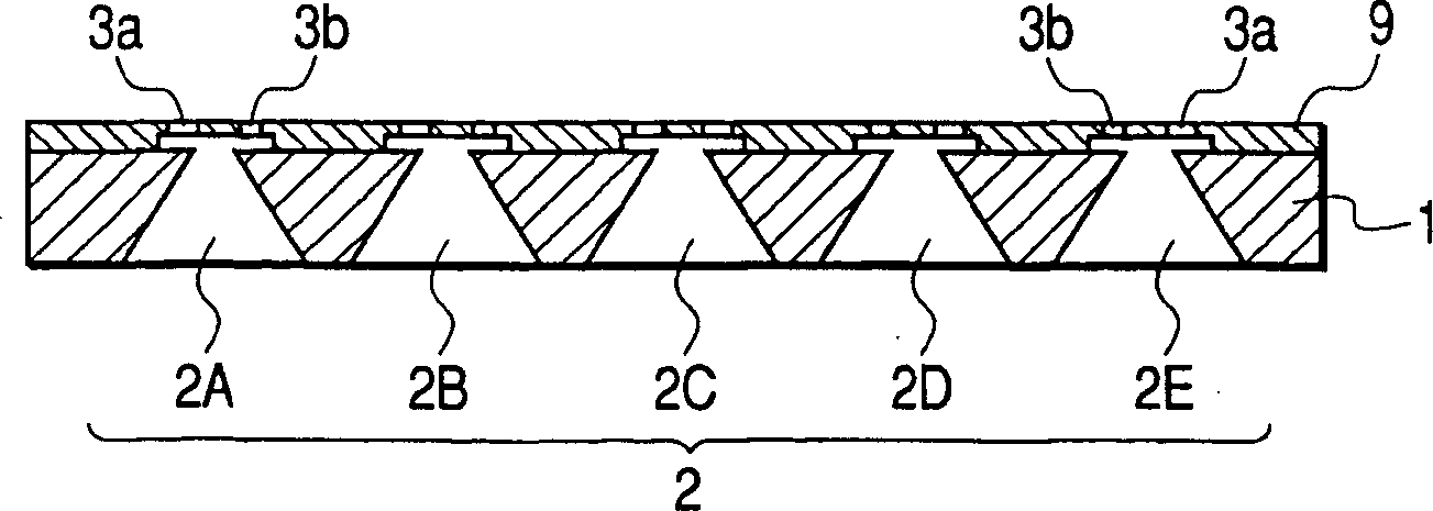
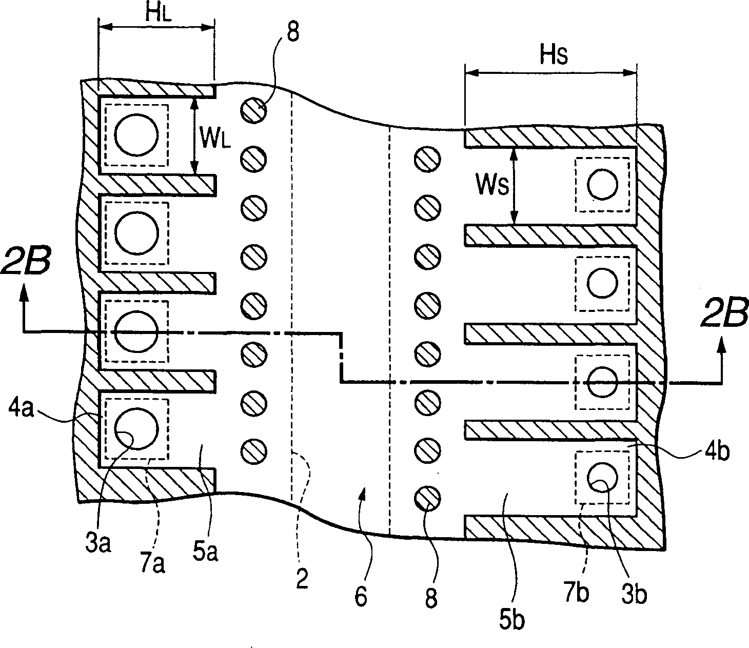
[0104]Figure 1A , 1B , 2A, and 2B represent the ink jet recording head of Reference Example 1. As shown in Figure 1, the basic structure of the inkjet recording head is: five ink supply ports 2 are provided on a single substrate 1, and cyan ink is supplied at the ink supply ports 2A and 2E, and cyan ink is supplied at the ink supply ports 2B and 2D. Magenta ink and yellow ink are supplied from the ink supply port 2C. On the discharge port plate 9 bonded to the substrate 1, for each ink supply port 2, a large droplet discharge port 3a for discharging a large droplet and a small droplet discharge port for discharging a small droplet are respectively provided. 3b. For ink supply ports 2A and 2B, the Figure 1A and 1B The left side is provided with a large droplet ejection port 3a, in Figure 1A and 1B The right side is provided with the small droplet discharge port 3b, and for the ink supply ports 2D and 2E, in Figure 1A and 1B The left side is provided with small droplet e...
reference example 2
[0137] Below, refer to Figure 3A and 3B The ink jet recording head of Reference Example 2 will be described. The description of the same parts as those in Reference Example 1 is omitted.
[0138] In this reference example, H L =H S And W L >W S . contains WS The dimensions of each part were obtained by the same calculation as in Reference Example 1.
[0139] In reference example 1, there is the problem that the ink flow channel 5b for small liquid droplets becomes long, and the whole inkjet recording head becomes larger. In this reference example, the ink for small liquid droplets can be increased without increasing the size of the inkjet recording head. Flow resistance S of channel 5b Sb .
Embodiment 1
[0141] Below, refer to Figure 4A and 4B Embodiment 1 of the ink jet recording head of the present invention will be described. Descriptions of the same parts as those in Reference Examples 1 and 2 are omitted.
[0142] In this example, H L =H S And W L >W S , the width of the small droplet ink channel 5b is narrower than the width of the small droplet pressure chamber 4b. That is, the large droplet ink flow channel 5a is directly connected to the large droplet pressure chamber 4b with the same width, and the small droplet ink flow channel 5b is narrower than the small droplet pressure chamber 4b, serving as a throttling portion for ink flow. In addition, the dimension of each part was determined by the calculation similar to reference example 1.
[0143] In the structure of Reference Example 2, the overall width of the ink flow channel 5b for small droplets is narrowed, and the shape of the heater 4b becomes slender, and there are constraints in the size design of the ...
PUM
 Abstract
Description
Claims
Application Information
 - R&D
- Intellectual Property
- Life Sciences
- Materials
- Tech Scout
- Unparalleled Data Quality
- Higher Quality Content
- 60% Fewer Hallucinations
Browse by: Latest US Patents, China's latest patents, Technical Efficacy Thesaurus, Application Domain, Technology Topic, Popular Technical Reports.
© 2025 PatSnap. All rights reserved.Legal|Privacy policy|Modern Slavery Act Transparency Statement|Sitemap|About US| Contact US: help@patsnap.com


