Electric wire connector

A connector and wire technology, applied in the field of wire connectors, can solve problems such as poor operability and poor operability, and achieve the effects of preventing misoperation, preventing falling off, and improving operability

Inactive Publication Date: 2003-11-05
ORMON CORP
View PDF1 Cites 8 Cited by
  • Summary
  • Abstract
  • Description
  • Claims
  • Application Information

AI Technical Summary

Problems solved by technology

For this reason, two different operations are required for attaching and detaching the electric wire 31, that is, a pressing operation and a pulling operation must be performed, and the operability is poor.
In particular, when restoring the release button, it is necessary to use a pull-back force greater than the pressing force required for pressing the release button 11, 25, so there is a problem that the operability is worse.

Method used


Image

  • Electric wire connector
  • Electric wire connector
  • Electric wire connector

Examples


Embodiment Construction

[0027] The following according to Figure 1 to Figure 8 Examples of the present invention will be described.

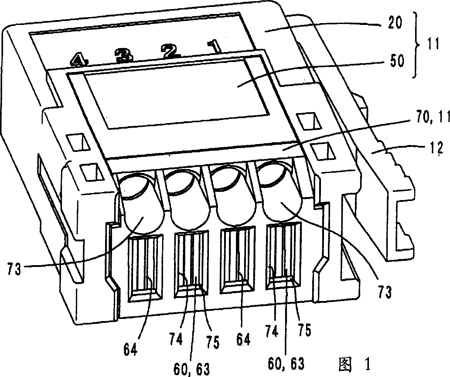
[0028] The first embodiment of the present invention is shown in Fig. 1 to Figure 4 Shown is the situation applicable to the wire connector 10 .

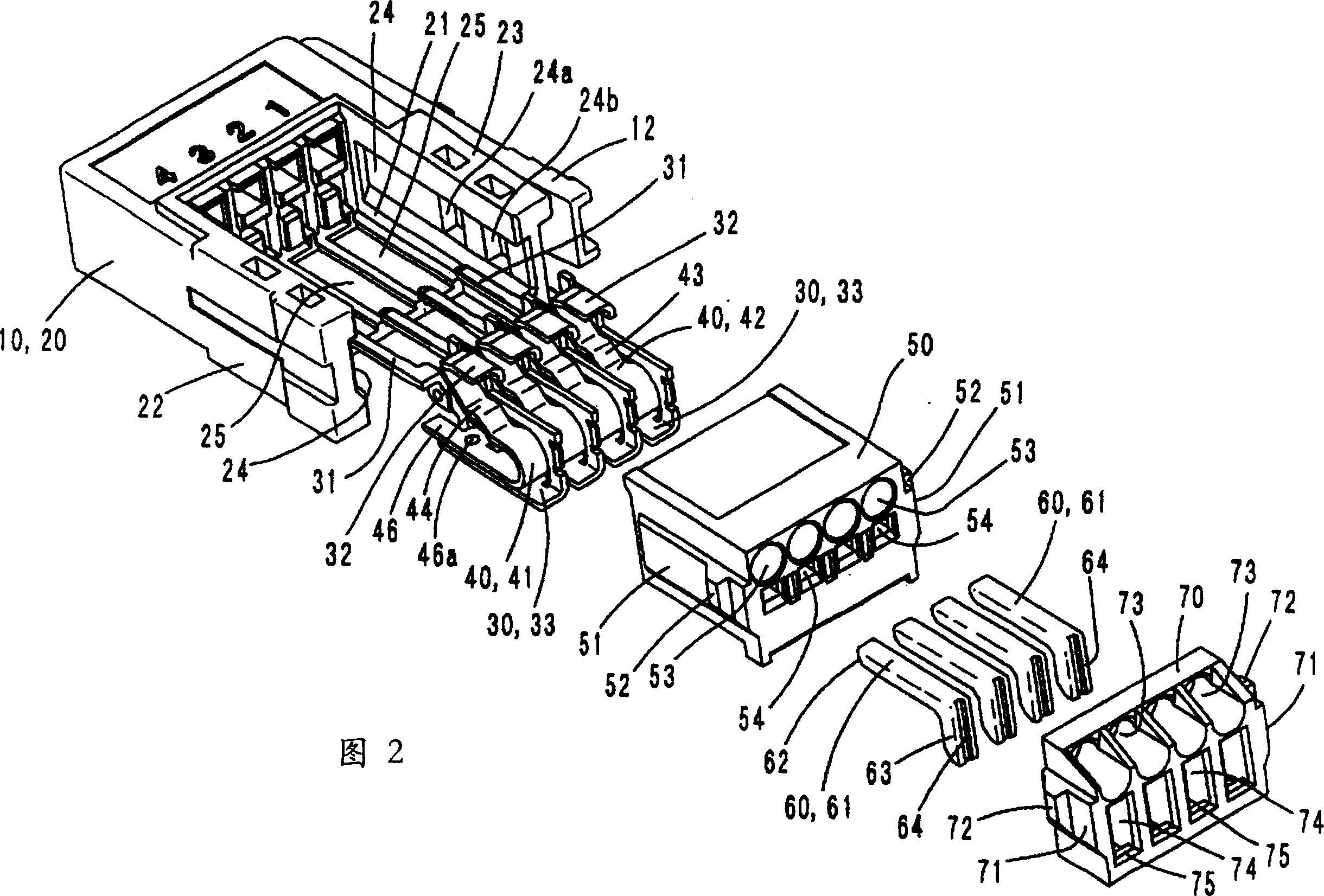
[0029] The wire connector 10, as shown in FIG. 2 , is equipped with a metal connector 30 , a leaf spring 40 and an operating rod 60 in an internal space formed by installing a cover 70 on a box body 11 composed of a housing 20 and a base 50 . . In addition, 12 is a lock lever.

[0030] The housing 20 is a resin molded product in which a concave portion 21 capable of engaging a base 50 and a cover 70 described later is provided on one side thereof. The casing 20 has guide grooves 24 , 24 formed on the inner surfaces of the arm portions 22 , 23 on both sides, respectively, and engaging recesses 24 a , 24 b are formed in the guide grooves 24 , respectively. The engagement recesses 24a, 24b are used to determine the posit...


PUM


Abstract

The present invention provides a wire connector that does not cause malfunction and has good operability. The electric wire connector installs the cover (70) on the box (11) formed by the housing (20) and the base (50), and houses the head (63) of the operating rod (60). Then, the cover (70) is provided with an opening operation hole (74) capable of pressing the head (63) of the operation lever (60) in the connected state toward the axial direction. Furthermore, an elongated hole (76) for wiring is provided between the case (11) and the cover (70) so that the head (63) of the operating lever (60) in the open state can be operated.

Description

technical field [0001] The present invention relates to a wire connector, in particular to a wire connector in which wires are clamped by a metal connector and a plate spring crimped thereon for electrical connection. Background technique [0002] Now, as an electric wire connector, for example, the relay type connector disclosed by Unexamined-Japanese-Patent No. 10-12294 is used. That is, it is a relay type connector constituted by a wire fixing device having housings 5, 19, terminals 7, 21, leaf springs 9, 23, and release buckles 11, 25. For example, the release button 11 is pressed into the box body 5 to elastically deform the leaf spring 9 , and then the wire 31 is inserted into the box body 5 . Then, the leaf spring 9 recovers its elasticity by pulling the release button 11 back, and the electric wire 31 is crimped and clamped by the terminal 7 and the leaf spring 9 to complete the electrical connection. [0003] However, in the relay type connector described above, t...

Claims


Application Information

Patent Timeline
Patent Type & Authority Applications(China)
IPC IPC(8): H01R4/48H01R9/03H01R13/50H01R13/648
CPCH01R13/501H01R4/48365H01R4/48455
Inventor 熊谷纯一郎横井川淳史
Owner ORMON CORP
Why Eureka
Try Eureka