Ink jet printer head and method and device for welding flexible printed circuit wire of printer head

An inkjet print head and welding device technology, which is applied in the structural connection of printed circuits, printed circuits, printed circuits, etc., can solve the problems of wire solder joints detachment and the decrease in stiffness of contact parts.

Inactive Publication Date: 2003-12-03
SAMSUNG ELECTRONICS CO LTD
View PDF2 Cites 2 Cited by
  • Summary
  • Abstract
  • Description
  • Claims
  • Application Information

AI Technical Summary

Problems solved by technology

[0005] In addition, when the welding tool is in partial contact with the wire during thermosonic welding, the contact portion where the vibration energy generated by the ultrasonic waves on the wire converges will be deformed, and the rigidity of the contact portion will decrease, so that the The wire will easily detach from the solder joint

Method used


Image

  • Ink jet printer head and method and device for welding flexible printed circuit wire of printer head
  • Ink jet printer head and method and device for welding flexible printed circuit wire of printer head
  • Ink jet printer head and method and device for welding flexible printed circuit wire of printer head

Examples


Embodiment Construction

[0033] Hereinafter, the inkjet printhead will not be described, but it can be understood by describing the welding method and apparatus according to the present invention.

[0034] The present invention mainly uses thermocompression welding to replace thermosonic welding, that is, to replace thermosonic welding using local kinetic energy. In thermocompression welding, the fragile substrate is no longer subjected to oscillating shocks, so that, contrary to thermosonic welding, several solder joints can be welded simultaneously.

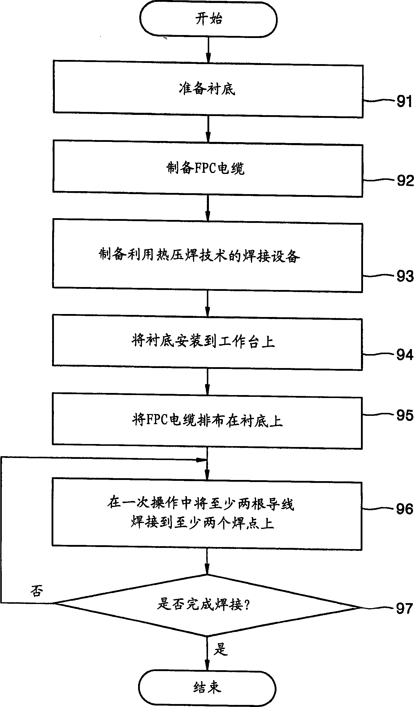
[0035] figure 2 is a flowchart for illustrating the welding method according to the present invention. refer to figure 2 , firstly, in step 91, a substrate for an inkjet print head is prepared. Subsequently, a flexible printed circuit (FPC) cable to be soldered to the substrate is prepared in step 92 . Next, in step 93, a welding device is prepared for welding the wires in the FPC cable to the welding points of the substrate by using the thermoco...


PUM


Abstract

An ink jet print head, a method of bonding a flexible printed circuit (FPC) cable for an ink jet print head, and an apparatus adopting the method are provided. In this bonding method, the bonding portion of an FPC conductor is heated being pressed down on a corresponding pad formed on a substrate for an ink jet print head. Then, at least two pads are bonded at a time. In this bonding method, an electrical defect due to pad peel-off phenomenon, which is created by an conventional tape automated bonding (TAB) method in which the conductors of an FPC cable are bonded to the pads on a substrate in a manner where one conductor is bonded to a pad at a time, is removed to increase the reliability of bonding. In addition, the bonding of a plurality of pads at a time leads to a reduction in the time required for bonding.

Description

technical field [0001] The present invention relates to an inkjet printhead, a method for soldering a flexible printed circuit (FPC) cable for an inkjet printhead, and an apparatus using the method. Background technique [0002] In the inkjet printhead employing the electro-thermal conversion technology, which utilizes bubbles obtained by instantaneously heating the ink to Discharge ink droplets. The substrate also includes a plurality of signal wires electrically connected to the heating device, and a plurality of electric pads arranged on the edge of the substrate in a straight line, so as to realize the connection between the signal wires and an external circuit. s contact. [0003] The welding spots are connected to an FPC cable, and a plurality of wires corresponding to the welding spots are arranged side by side on the FPC cable. The solder joints are bonded to the wires by a thermosonic bonding operation. [0004] US Patent Nos. 4,635,073 and 6,126,271 disclose a ...

Claims


Application Information

Patent Timeline
Patent Type & Authority Applications(China)
IPC IPC(8): B41J2/16B41J2/045B41J2/055B41J2/14H05K1/14H05K3/32H05K3/36
CPCH05K2203/0195H05K3/361H05K1/147B41J2/14072H05K2201/0397H05K3/328H05K2201/0367B41J2/16
Inventor 金正珗曹瑞铉孙大雨姜思尹郑明松
Owner SAMSUNG ELECTRONICS CO LTD
Why Eureka
Try Eureka