Radio base station and communication terminal
A wireless base station and communication terminal technology, applied in wireless communication, selection device, multiplex communication, etc., can solve the problems of impossible accurate measurement of delay envelope, reduced spectrum efficiency, insufficient time resolution, etc.
- Summary
- Abstract
- Description
- Claims
- Application Information
AI Technical Summary
Problems solved by technology
Method used
Image
Examples
Embodiment 1
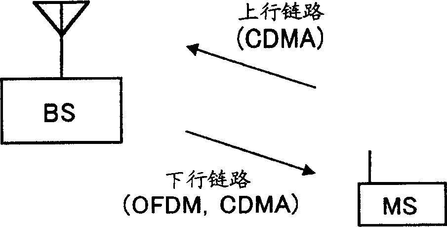
[0024] In this embodiment, CDMA is used as an uplink access system, and the base station generates an accurate delay envelope to determine the guard interval.
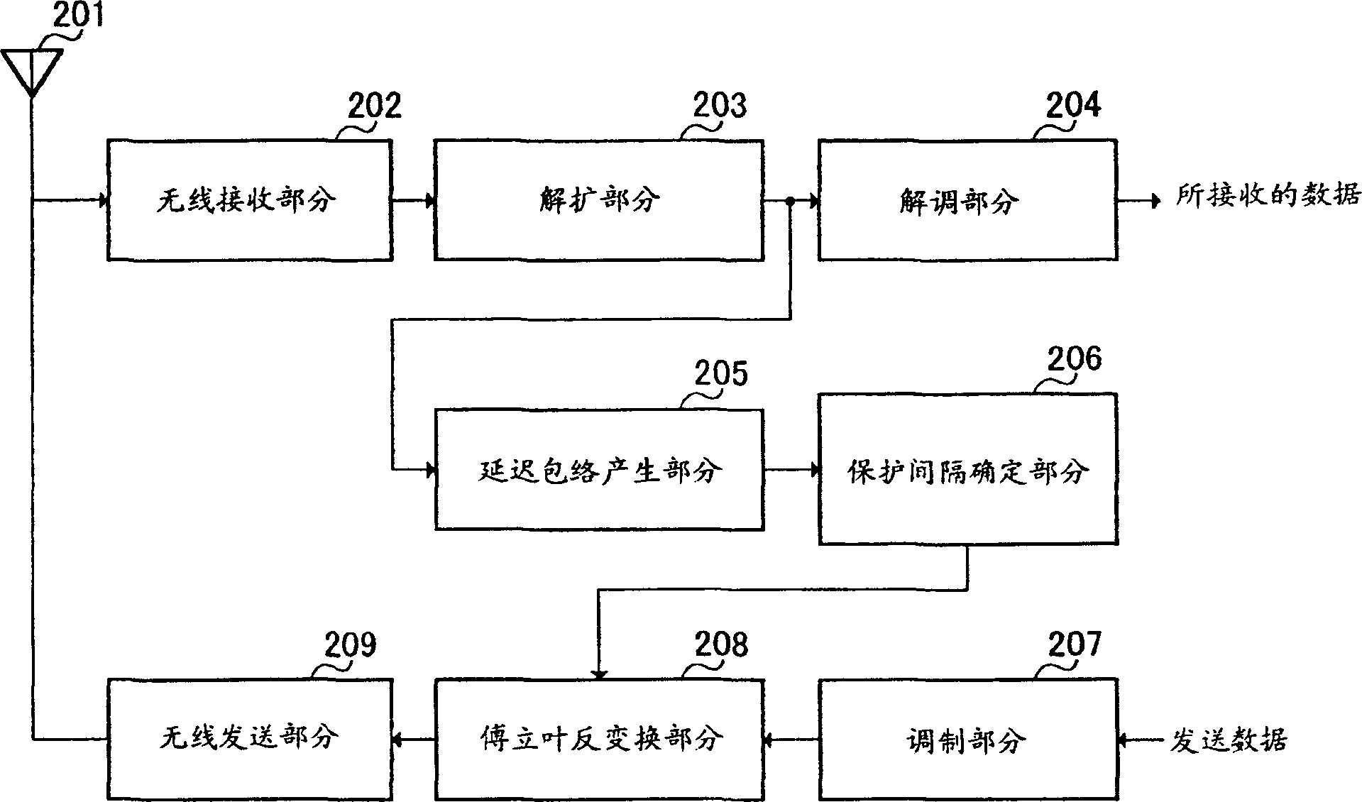
[0025] figure 2 is a block diagram of the configuration of the radio base station apparatus (hereinafter, abbreviated as BS if necessary) of Embodiment 1 of the present invention.
[0026] Wireless reception section 202 receives an uplink signal transmitted from a communication terminal device (hereinafter, abbreviated as MS if necessary) via antenna 201 . The radio reception section 202 performs predetermined reception processing (eg, frequency down conversion and A / D conversion) on the uplink signal, and outputs the radio reception processed signal to the despreading section 203 .
[0027] The despreading part 203 uses the same spreading code as the MS to despread the wirelessly received and processed signal, and outputs the despreading signal to the demodulation part 204 and the delay profile generation part 205 ....
Embodiment 2
[0047] In this embodiment, the leading part for generating the delay envelope is composed of a CDMA signal, and the data part is composed of an OFDM signal, and the two signals are multiplexed and then sent.
[0048] Figure 6 is a block diagram of the configuration of the BS according to Embodiment 2 of the present invention.
[0049] Wireless receiving section 602 receives an uplink signal transmitted from MS through antenna 601 . The radio reception section 602 performs predetermined reception processing (for example, frequency down conversion and A / D conversion) on the uplink signal, and outputs the radio reception processed signal to the despreading section 603 .
[0050] The despreading section 603 performs despreading on the wireless reception processed signal using the same spreading code as that of the MS, and outputs the despreading signal to the demodulation section 604 . Demodulation section 604 demodulates the despread signal, and outputs received data.
[0051...
Embodiment 3
[0082] This embodiment illustrates the use of information in the MS such as reception quality, Doppler shift, and envelope delay to determine OFDM transmission parameters (guard interval, subcarrier frequency spacing, and number of subcarriers), modulation scheme, and FEC coding rate situation.
[0083] Figure 10 It is a block diagram of the configuration of the BS according to Embodiment 3 of the present invention.
[0084] The radio receiving section 1002 receives an uplink signal transmitted by the MS through the antenna 1001 . Wireless reception section 1002 performs predetermined reception processing (such as down-conversion and A / D conversion) on the uplink signal, and outputs the wireless reception-processed signal to despreading section 1003 .
[0085] The despreading section 1003 performs despreading on the wireless reception processed signal using the same spreading code as that used in the MS, and outputs the despreading signal to the demodulation section 1004, t...
PUM
 Abstract
Description
Claims
Application Information
 - R&D
- Intellectual Property
- Life Sciences
- Materials
- Tech Scout
- Unparalleled Data Quality
- Higher Quality Content
- 60% Fewer Hallucinations
Browse by: Latest US Patents, China's latest patents, Technical Efficacy Thesaurus, Application Domain, Technology Topic, Popular Technical Reports.
© 2025 PatSnap. All rights reserved.Legal|Privacy policy|Modern Slavery Act Transparency Statement|Sitemap|About US| Contact US: help@patsnap.com


