Vacuum gripping apparatus and method for using same

A vacuum clamping and vacuum technology, which is applied in the direction of chucks, manufacturing tools, workpiece clamping devices, etc., can solve the problems of high cost and difficulty in manufacturing support plates, and achieve good flexibility.

Inactive Publication Date: 2003-12-31
HONG FU JIN PRECISION IND (SHENZHEN) CO LTD +1
View PDF5 Cites 40 Cited by
  • Summary
  • Abstract
  • Description
  • Claims
  • Application Information

AI Technical Summary

Problems solved by technology

However, in practical applications, it is necessary to design a support plate for each workpiece to be processed, and the co

Method used


Image

  • Vacuum gripping apparatus and method for using same
  • Vacuum gripping apparatus and method for using same
  • Vacuum gripping apparatus and method for using same

Examples


Embodiment Construction

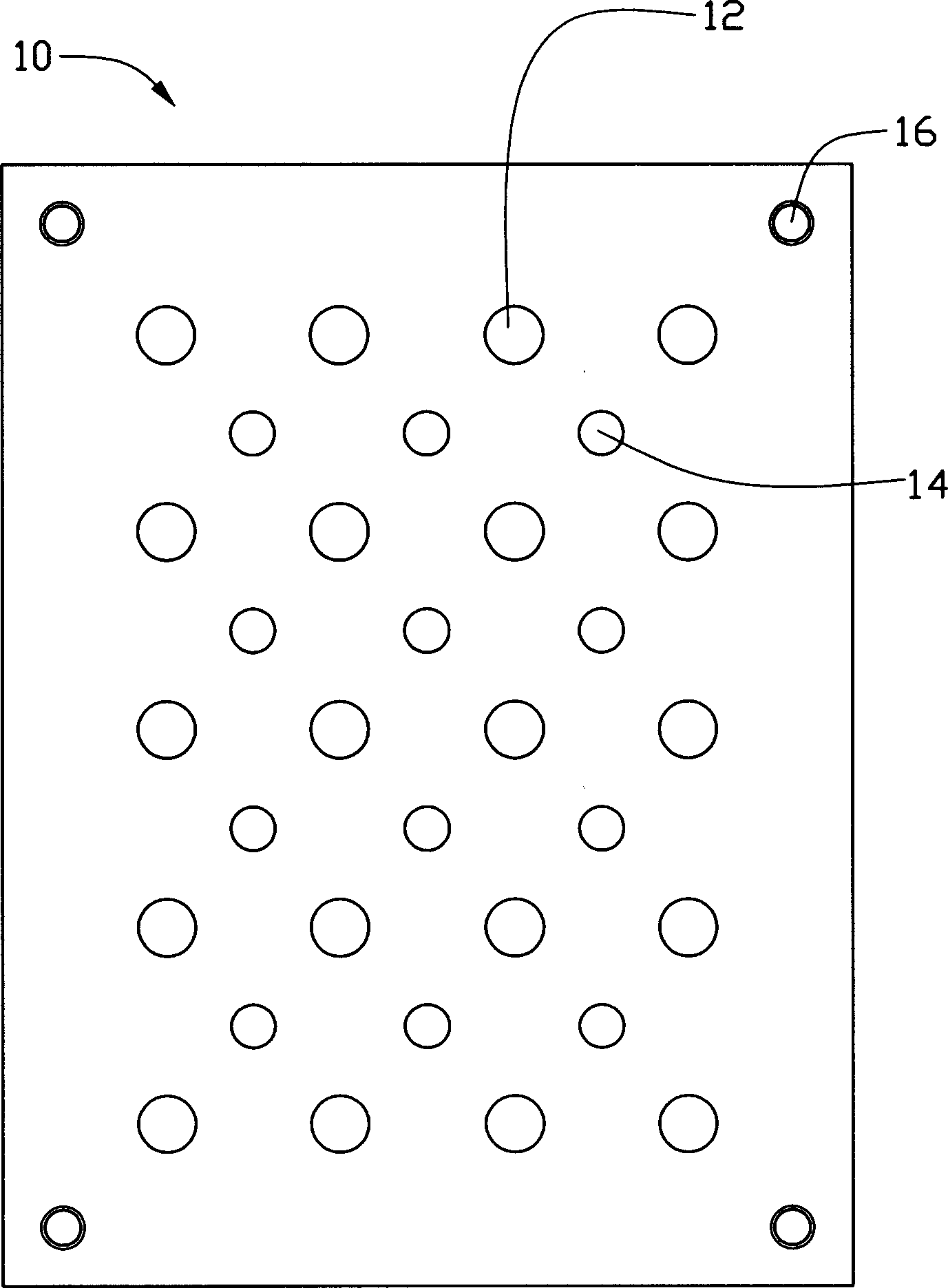
[0018] figure 1 It is the substrate 10 of the vacuum fixture of the present invention, and the four corners of the substrate 10 are provided with counterbore holes 16, and the substrate 10 can be fixed on a base (not shown) by passing through the counterbore holes 16 . A plurality of threaded holes 12 , 14 are formed through the base plate 10 .

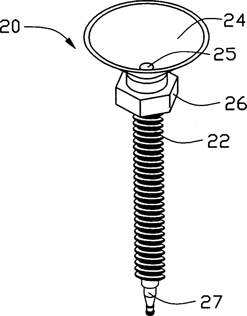
[0019] figure 2 It is the suction cup device 20 of the vacuum fixture of the present invention, and the suction cup device 20 includes an air guide tube 22 and a suction cup 24 connected to one end of the air guide tube 22 . The air guide tube 22 is made of rigid material, and its outer surface is provided with threads, and a swivel seat 26 with a larger cross-sectional area is integrally formed at one end close to the suction cup 24, and a trachea interface 27 is provided at the other end. The suction cup 24 is arranged on the end face of the rotating base 26 , the suction cup 24 is bowl-shaped and made of soft material, and an op...


PUM


Abstract

The vacuum fixture includes base board, chuck unit and support pins, the base board is provided with screw holes, the chuck unit includes chuck and air pipe connected to the chuck, and each of the support pins has head for supporting workpiece. Both the chuck unit and the support pins are provided with threads, so that the chuck unit and the support pins may be installed onto the base board via the screw holes. The height of the the chuck unit and the support pins relative to the base board may be regulated separately. After some workpiece is supported with the support pins, vacuum is applied to the chuck unit and the workpiece may be vacuum fixed.

Description

【Technical field】 [0001] The invention relates to a fixture for holding workpieces and a method for using the same, in particular to a vacuum fixture for absorbing workpieces with a suction cup and a method for using the same. 【technical background】 [0002] As the products of the 3C industry become lighter and thinner, if the traditional fixture is used to clamp and position the thinner and thinner products, the processing difficulty will become more and more difficult. Specifically, the traditional fixture is used to clamp and position the workpiece When it is used, it is easy to warp and deform the workpiece, and even cause damage. [0003] In order to solve the problems existing in the above-mentioned traditional clamps, the industry uses vacuum clamps to replace the traditional clamps to fix these thin parts. Although the term "vacuum" is conventionally used here, the reality is that the ideal vacuum is never achieved. A more common situation is a vacuum with an avera...

Claims


Application Information

Patent Timeline
IPC IPC(8): B25B11/00B25J15/06B65H9/08
Inventor 余杨新景张浚荣
Owner HONG FU JIN PRECISION IND (SHENZHEN) CO LTD
Why Eureka
Try Eureka