
Screen

A technology for screens and projection surfaces, which is applied to projection devices, instruments, and photometry using electric radiation detectors, etc., can solve the problems that the price of projectors is easy to increase, and achieve the effects of simplified structure, low price, and increased prices

Inactive Publication Date: 2004-01-21
SEIKO EPSON CORP
View PDF0 Cites 7 Cited by
  • Summary
  • Abstract
  • Description
  • Claims
  • Application Information

AI Technical Summary

Problems solved by technology

[0008] However, in such a correction on the projector side, a trapezoidal image is formed without using a part of the rectangular image forming area of ​​the light modulation device, and a rectangular projected image is formed by projecting it on a projection surface. Therefore, It cannot be said that the entire image forming area is effectively used
[0009] In addition, since such software needs to be installed in optical equipment such as a projector, there is a problem that the price of the projector is likely to increase.

Method used


Image

  • Screen
  • Screen
  • Screen

Examples


Embodiment 1

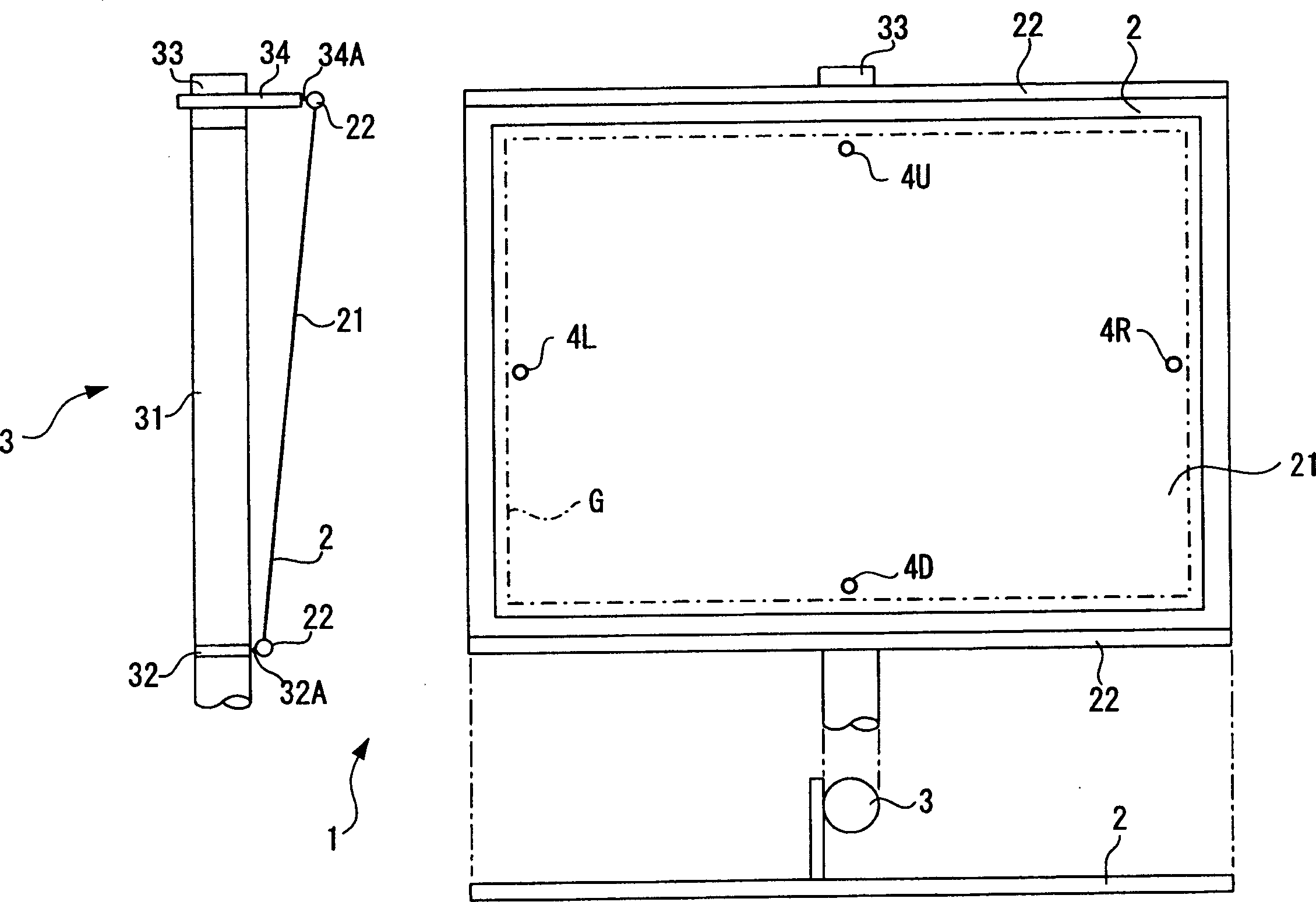
[0033] figure 1 Screen 1 showing an embodiment of the present invention.

[0034] This screen 1 is configured to include a screen main body 2 and pillars 3 .

[0035] The screen main body 2 as a projection surface includes: a white rectangular image forming surface 21 ; and frame members 22 provided along the upper and lower ends of the image forming surface 21 .

[0036] The image forming surface 21 is formed by embedding many fine glass beads on the white paint surface, and the frame member 22 is provided to prevent the image forming surface 21 from being bent when projecting an optical image from an optical device such as a projector. .

[0037] Four light quantity sensors 4U, 4D, 4L, and 4R as light quantity detection means are provided near the outer periphery of the image forming surface 21 of the screen main body 2 .

[0038] Of the four light sensors 4U, 4D, 4L, 4R, the light sensors 4U, 4D are arranged vertically to the image forming surface 21 , and the light sens...

Embodiment 2

[0085] Next, Embodiment 2 of the present invention will be described. In the following description, the same reference numerals are assigned to the same members and parts as those already described, and description thereof will be omitted.

[0086] In the first embodiment described above, the light quantity sensors 4U, 4D, 4L, and 4R are connected in parallel to the current detection unit 71 .

[0087] In contrast, the light quantity sensors 5U, 5D, 5L, and 5R of Embodiment 2 are as Figure 7 As shown in FIG. 2 , a bridge circuit is configured in which the photodiode 41 of each sensor is used as a resistance element. The configuration of the light sensor 5U, 5D, 5L, and 5R on the screen is the same as that in Embodiment 1. The light sensor 5U is on the upper side of the screen, the light sensor 5D is on the lower side of the screen, the light sensor 5L is on the left side of the screen, and the light sensor 5R is on the right side of the screen. side.

[0088] In this bridg...


PUM


Abstract

A screen having a projection surface on which a light beam irradiated by an optical equipment such as a projector is projected to form a projection image has luminous energy sensors (4U, 4D, 4L, 4R) and an attitude controller (70) for controlling the attitude of the projection surface based on the luminous energy detected by the luminous energy sensors (4U, 4D, 4L, 4R), in which, since the luminous energy sensors (4U, 4D, 4L, 4R) and the attitude controller (70) are provided, the attitude of the projection surface can be controllably adjusted by detecting the luminous energy of the projection image from the optical equipment, so that the projection surface of the screen can be correctly positioned relative to the optical equipment, thus automatically correcting trapezoidal distortion etc. of the projection image.

Description

technical field [0001] The present invention relates to a screen having a projection surface on which a light beam emitted from an optical device such as a projector is projected to form a projected image. Background technique [0002] Conventionally, optical equipment such as a projector having a light modulation device that modulates a light beam emitted from a light source based on image information and that enlarges and projects the light beam modulated by the light modulation device has been widely used in presentations and the like. [0003] The light beams emitted from these optical devices are projected onto the projection surface of the screen to form a projection image, and by thus enlarging and projecting onto the projection surface, presentations to many people can be effectively performed. [0004] In the state where the light beam emitted from such an optical device is projected onto the projection surface of the screen, if the optical device does not face the ...

Claims


Application Information

Patent Timeline
Patent Type & Authority Applications(China)
IPC IPC(8): G03B21/56
CPCG03B21/56
Inventor 小林诚
Owner SEIKO EPSON CORP
Learn More