A dental floss holder

A holder and floss technology, applied in the directions of flossing, dentistry, cleaning teeth, etc., can solve the problems of inconvenient handles, inconvenient cleaning of teeth, and not taking into account the angle of the mouth.

Inactive Publication Date: 2004-01-21
埃里克福塞尔
View PDF4 Cites 5 Cited by
  • Summary
  • Abstract
  • Description
  • Claims
  • Application Information

AI Technical Summary

Problems solved by technology

Therefore, the handle is inconvenient when cleaning teeth at the back of the mouth unless the bracket is installed in the opposite direction
This arch is small and does not take into account the curvature of the mouth, so it is not convenient for cleaning the teeth in the back of the mouth

Method used


Image

  • A dental floss holder
  • A dental floss holder
  • A dental floss holder

Examples


Embodiment Construction

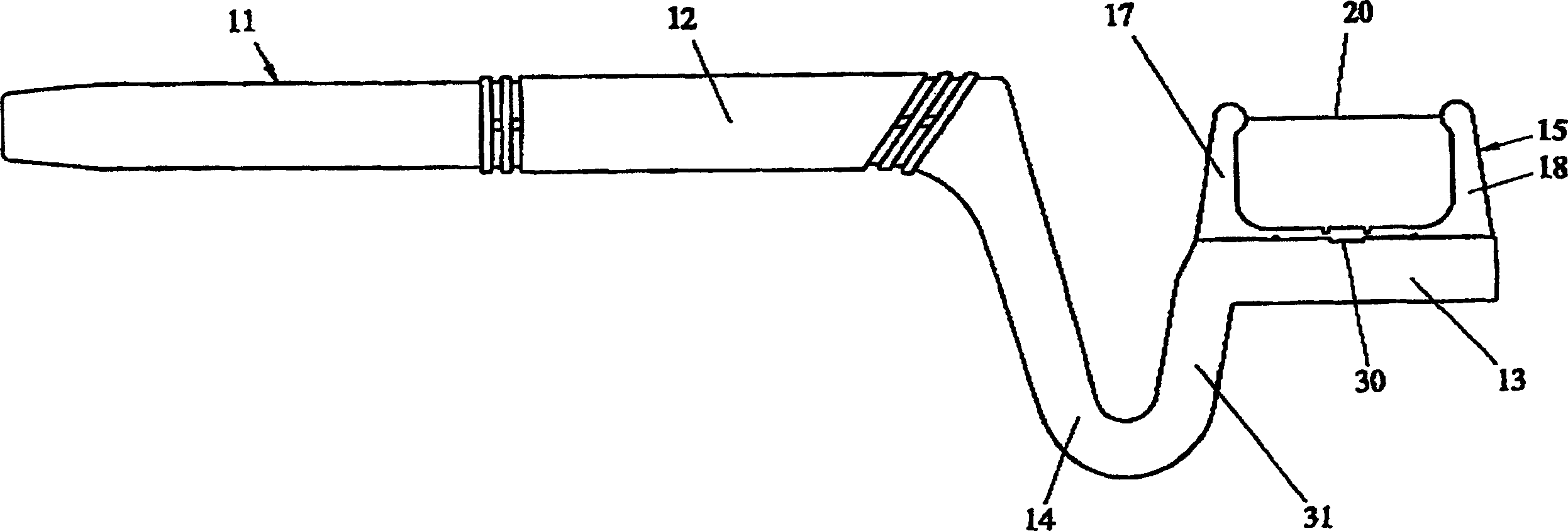
[0012] like figure 1 The floss holder shown has a handle 11 having a gripping portion 12, and a mounting portion 13 for a bracket 15. The handle has a bow 14 between the grip portion and the mounting portion. Bracket 15 single indicated in the Figure 5 middle. figure 2 Shown is another design of bracket 15. handle 11 for as figure 2 bracket 40 shown as well as for Figure 5 The brackets 15 shown are identical. In the two drawings, the same components are denoted by the same reference numerals.

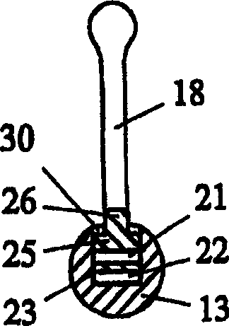
[0013] like figure 2 The bracket 40 shown is mounted on a image 3 and 4 in the handle shown. The bracket 40 is U-shaped and comprises a base 16 and two legs 17 , 18 . These two struts are thinner than the base, so that the base can be inserted axially into an axial groove, namely into a keyhole-shaped groove 19 in the mounting part 13 of the handle. The base 16 then becomes part of the bracket for clamping the bracket to the handle. The dental floss 20 is mounted betw...


PUM


Abstract

A dental floss holder comprises a handle (11) and a cartridge (15, 40, 41, 42). The cartridge is U-formed and has a dental floss (20) fastened between its two legs (17, 18). The base (16) of the cartridge is somewhat bow-formed and arranged to be pushed into a straight groove (19) in the handle, and the dental floss is then automatically tensioned because the mounting forces the legs apart.

Description

technical field [0001] The present invention relates to a dental floss holder comprising a handle and a bracket with a base, two legs, and a dental floss (dental floss holder) suspended between the two legs. dental floss). Background technique [0002] US5579786A, US5170809A and US5246021A all describe dental floss holders. None of the floss holders in these publications describe the tension of the floss. US5170809A describes a handle with a small bow, the depth of the bow from the handle is as large as the length of the strut. This handle does not take into account the curved corners of the mouth, so it is very inconvenient for cleaning the teeth in the back of the mouth. US3892249A describes a floss holder in which the floss is stretched somewhat too tight when the floss holder is installed. The handle in its figure 12 has a bow, but this bow is not in the plane of the strut. Therefore, the handle is inconvenient when cleaning teeth at the back of the mouth unless the...

Claims


Application Information

Patent Timeline
Patent Type & Authority Applications(China)
IPC IPC(8): A61C15/04
CPCA61C15/048A61C15/046A61C15/04
Inventor 埃里克·福塞尔
Owner 埃里克福塞尔
Why Eureka
Try Eureka