
Shackle and method for stabilizing a vehicle during transport

Active Publication Date: 2016-10-27
HON CHARLIE R
View PDF0 Cites 4 Cited by
  • Summary
  • Abstract
  • Description
  • Claims
  • Application Information

AI Technical Summary

Benefits of technology

The patent text describes a device that can securely attach a cable to a vehicle's handlebars or handgrip, allowing the cable to attach from multiple directions and with strong tension to stabilize the vehicle during transport. This device minimizes damage to the vehicle and provides a flexible and secure anchoring point.

Problems solved by technology

However, most motorcycles do not have any readily available point of attachment for tie downs in transporting the motorcycles.
It is known that prior art motorcycle restraint devices often scratch or indent the motorcycle when the restraint is fastened to the handle bar.
Often a tie-down rod includes hose clamps and a pins which, when secured to the frame of the motorcycle, scratch the paint on the frame and possibly indent the frame.
This is not conducive to a stable anchoring point for the tie down cable.
However, this terminal cupping arrangement is not effective with motorcycles with bar end attached hand / lever guard because the bar end access is being blocked by the attached hand / lever guard.
Yet another problem is that the tie-downs are generally made of nylon, leather or other slightly elastic material.
However, compression of the motorcycle forks is undesirable and causes damage over a long period of time.
Current methods and apparatii do not readily provide a stabilizing device that hingedly clamps around a linear member of a vehicle to form a detachably attached anchoring point on the vehicle that enables a tethered cable to securely fasten to the device from multiple directions and with strong tensions for stabilizing the vehicle during transport.

Method used


Image

  • Shackle and method for stabilizing a vehicle during transport
  • Shackle and method for stabilizing a vehicle during transport
  • Shackle and method for stabilizing a vehicle during transport

Examples


Embodiment Construction

[0038]Reference throughout this specification to “one embodiment,”“an embodiment,” or similar language means that a particular feature, structure, or characteristic described in connection with the embodiment is included in at least one embodiment of the present invention. Thus, appearances of the phrases “in one embodiment,”“in an embodiment,” and similar language throughout this specification may, but do not necessarily, all refer to the same embodiment.

[0039]Furthermore, the described features, structures, or characteristics of the invention may be combined in any suitable manner in one or more embodiments. In the following description, numerous specific details are provided to provide a thorough understanding of embodiments of the invention. One skilled in the relevant art will recognize, however, that the invention may be practiced without one or more of the specific details, or with other methods, components, materials, and so forth. In other instances, well-known structures, ...


PUM


Abstract

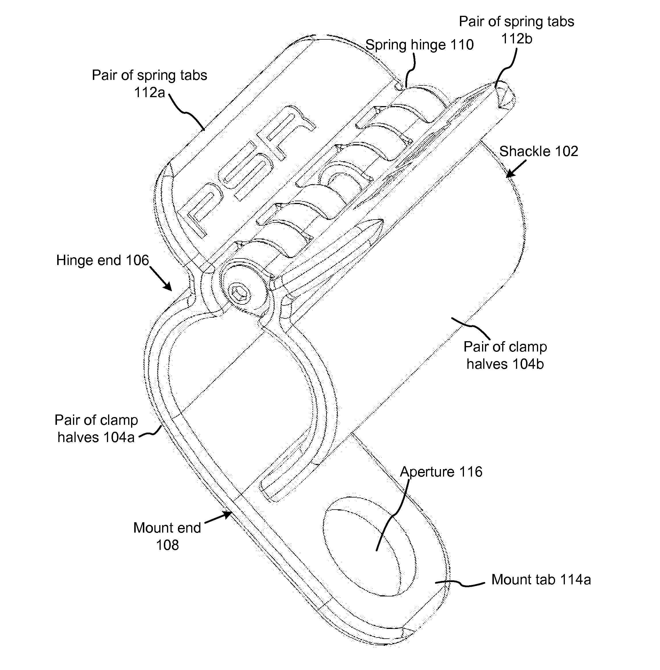
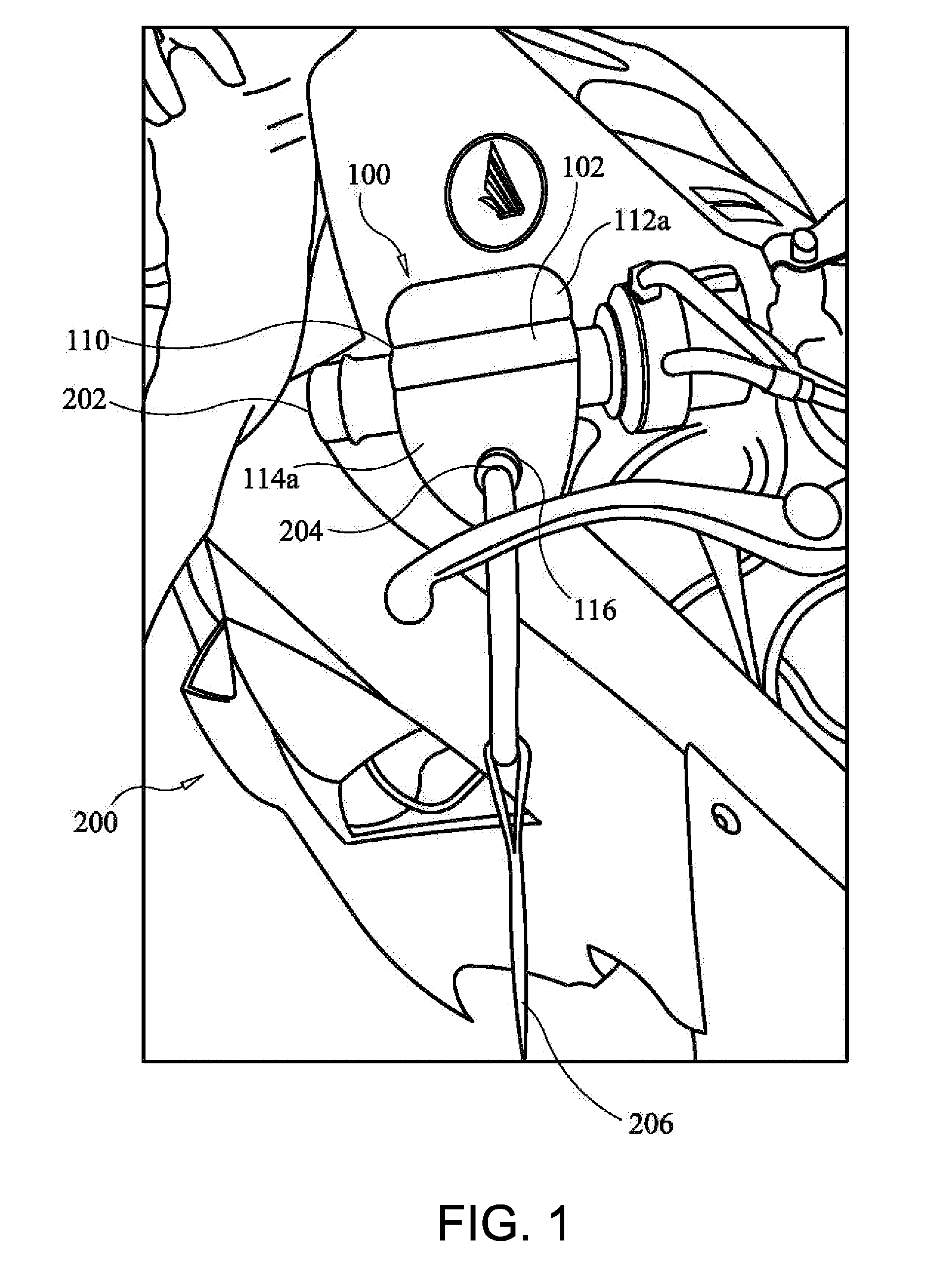
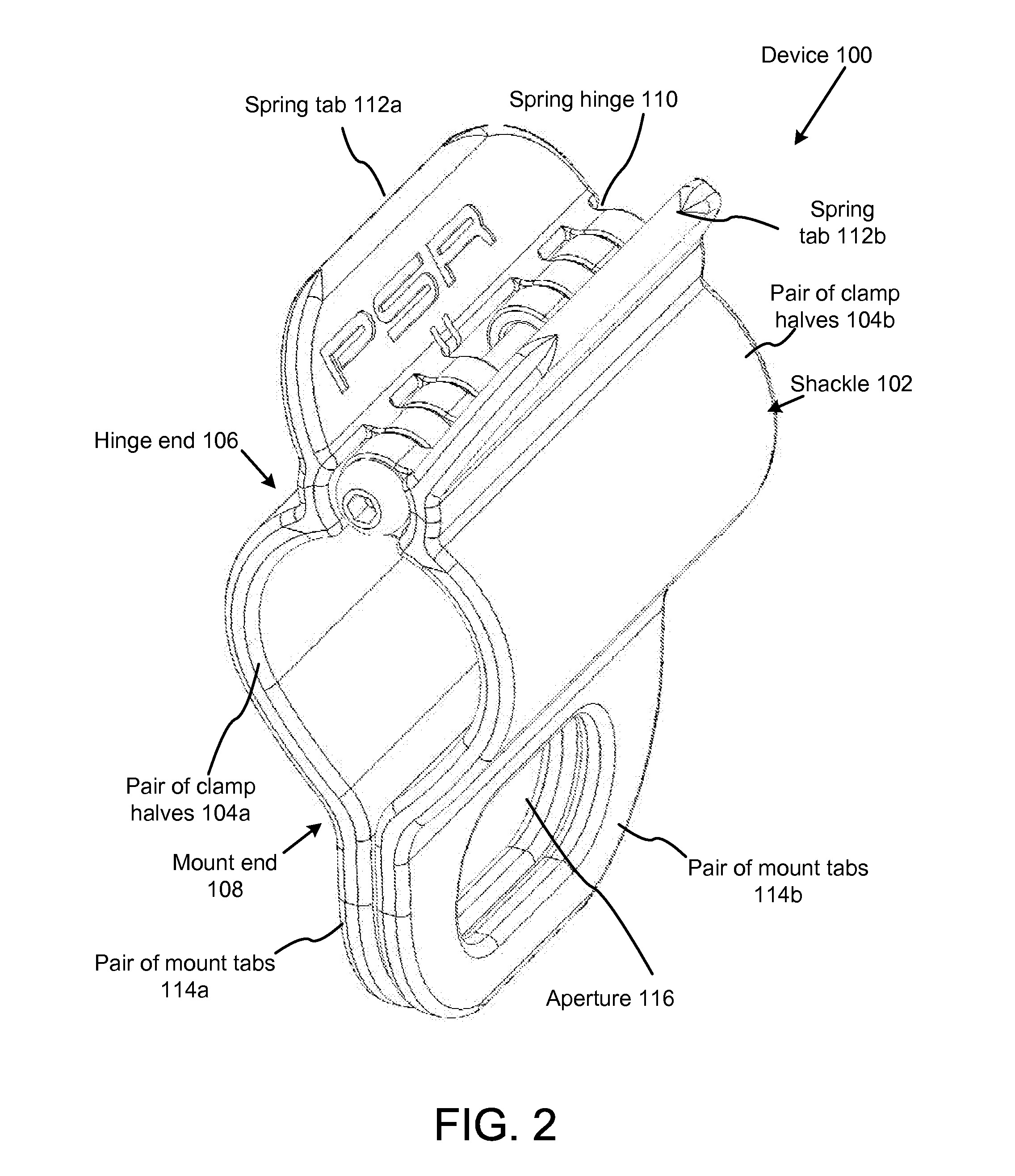
A device and method for stabilizing a vehicle during transport provides a detachably attached anchoring point on a vehicle for a tethered cable to securely fasten to from multiple directions and with strong tensions on the tethered cable. This creates a unique anchor on the vehicle that helps stabilize the vehicle during transport while minimizing damage to the vehicle. The device utilizes a biased, spring hinge to pivotally enclose a linear member, such as a grip, on the vehicle. A fastener at the terminus of the cable flexibly and detachably joins with the device at apertures. Tabs extend from the device to facilitate gripping for moving the device between an open and a closed position. The device may detachably attach to multiple areas of the vehicle, and multiple devices may be used throughout the vehicle. These flexible, multi-positional features of the device increase the effectiveness of the tethered cables.

Description

FIELD OF THE INVENTION[0001]This invention relates to a device and method for stabilizing a vehicle during transport, and more particularly relates to a device that hingedly clamps around a linear member of a vehicle to form a detachably attached anchoring point on the vehicle that enables a tethered cable to securely fasten to the device from multiple directions and with strong tensions for stabilizing the vehicle during transport.DESCRIPTION OF THE RELATED ART[0002]Typically, the fastening or securing of a load to its carrier by use of ropes, cables, or other means is used to prevent shifting or damage to a vehicle during transport. Tie down cables are especially effective to hold down motorcycles during transport. The tie down cables generally anchor to the transporting vehicle from one end, and to the motorcycle from an opposite end. Generally, the tension created on the cable maintains the motorcycle in a desired upright position.[0003]It is known in the art that motorcycles ar...

Claims


Application Information

Patent Timeline
IPC IPC(8): B60P3/073B60P7/08
CPCB60P3/073B60P7/08B60P3/079
Inventor HON, CHARLIE R.
Owner HON CHARLIE R
Learn More