Torch with rotational start

Inactive Publication Date: 2005-04-19
THERMAL DYNAMICS
View PDF6 Cites 32 Cited by
  • Summary
  • Abstract
  • Description
  • Claims
  • Application Information

AI Technical Summary

Benefits of technology

[0012]Furthermore, among the several objects and features of the present invention is to provide a plasma torch having a rotational starting mechanism designed to maintain proper alignment and axial spacing between the electrode and the torch tip; to provide such a mechanism in which a pilot arc is generated through contact starting by relative rotational movement between the electrode and tip rather than by relative axial movement therebetween; to provide such a mechanism wherein the electrode and tip are economical to manufacture and thus inexpensive to replace; to provide a consumable electrode of unique configuration which may be used in the aforementioned mechanism; and to provide a consumable tip of unique configuration which may be used in the aforementioned mechanism.
[0013]Briefly, the plasma torch having a rotational starting mechanism in accordance with the present invention comprises a cathode having a central longitudinal axis, an electrode mounted axially on the cathode, a tip mounted axially on the torch, and a rotating mech

Problems solved by technology

When a sufficiently high voltage is applied to the electrode, an arc is caused to jump the gap between the electrode and the torch tip, thereby heating the gas and causing it to ionize.
However, it is expensive to perform a threading operation on consumable items such as electrodes.
Furthermore, a threaded electrode is prone to errors in centering the electrode on the axis of the plasma torch.
In any event, supplying two separate fluids within the same torch increases the cost of manufacturing and operating the torch.
Thus, replacing the tip assembly to adjust the ratio of plasma gas flow volume to secondary gas flow volume is cumbersome and time-consuming because it requires the operator to replace a plurality of items.
Among

Method used


Image

  • Torch with rotational start
  • Torch with rotational start
  • Torch with rotational start

Examples


Embodiment Construction

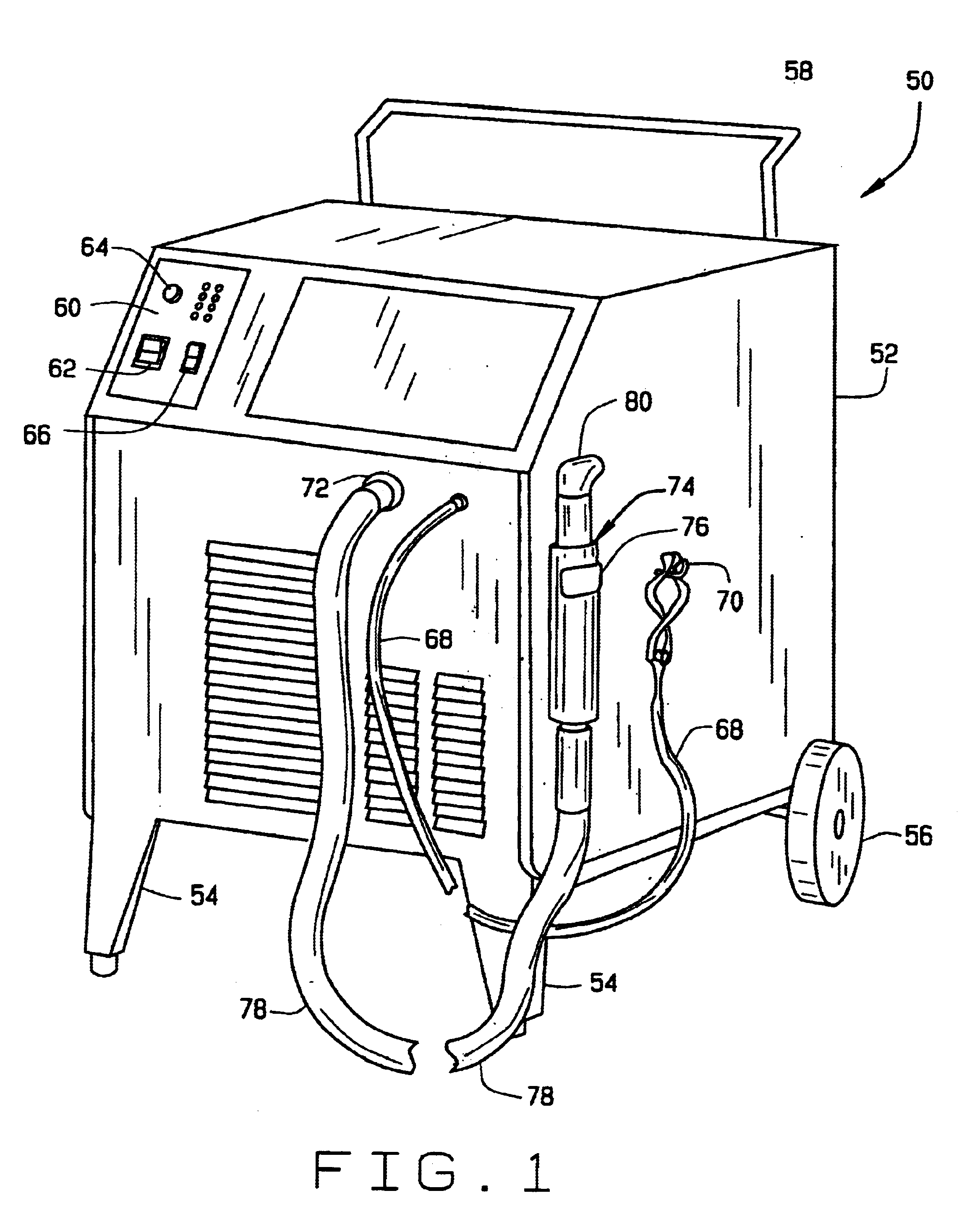
[0073]Referring to FIG. 1, a plasma cutting system of the present invention is designated generally by reference numeral 50. The cutting system includes a portable housing 52 having a pair of front legs 54 and a pair of rear wheels 56. A handlebar 58 is provided at the rear of the housing for tilting the housing rearwardly and transporting the cutting system to another location. A control panel 60 is provided at the front of the housing for convenient operation of the cutting system. The control panel may include an on / off power switch 62, a rheostat 64 for selecting a variable output current, and an on / off switch 66 for the gas supply. A power supply is disposed inside the housing, and a ground wire 68 can be clipped to a hook 70 on the side of housing 52. Gas from an external source (not shown) is provided to the cutting system through an inlet port (not shown) on housing 52. Typically, the gas is either oxygen or nitrogen, but other suitable gases are known to those skilled in th...


PUM

PropertyMeasurementUnit
Forceaaaaaaaaaa
Widthaaaaaaaaaa
Depthaaaaaaaaaa

Abstract

A plasma arc torch has a threadless electrode-cathode locking assembly, a one-piece tip assembly, and a rotational contact starting mechanism. The cathode and electrode of the locking assembly are configured such that relative rotation of the electrode with respect to the cathode causes the electrode to move in an axial direction relative to the cathode for locking the electrode in fixed axial and rotational position with respect to the cathode. The inner wall of the one-piece tip assembly is configured to receive the forward end of the electrode in a non-contact position. Rotation of the electrode with respect to the tip causes an arcing formation on the electrode to contact an arcing chamber within the cavity. Rotation of the electrode away from the tip generatesa pilot arc in the arcing chamber.

Description

FIELD OF INVENTION[0001]The present invention relates generally to plasma arc torches and, in particular, to plasma arc torches having a threadless electrode-cathode locking assembly, a one-piece tip assembly with flow passaging sized to provide a selected ratio of plasma gas flow volume to secondary gas flow volume and a rotational contact starting mechanism.BACKGROUND OF THE INVENTION[0002]Plasma torches, also known as electric arc torches, are commonly used for cutting and welding metal workpieces by directing a plasma consisting of ionized gas particles toward the workpiece. In a typical plasma torch, a gas to be ionized is supplied to the front end of the torch and flows past an electrode before exiting through an orifice in the torch tip. The electrode, which is a consumable part, has a relatively negative potential and operates as a cathode. The torch tip is adjacent to the end of the electrode at the front end of the torch and constitutes a relatively positive potential anod...

Claims


Application Information

Patent Timeline
IPC IPC(8): H05H1/26H05H1/34
CPCH05H1/34H05H2001/3489H05H2001/3442H05H1/3442H05H1/3489
Inventor HORNER-RICHARDSON, KEVIN D.GRANT, PEARL A.HEWETT, ROGER W.HEWES, GENE V.HORN, HOWARD H.
Owner THERMAL DYNAMICS
Why Eureka
Try Eureka