Sheet metal tie

Inactive Publication Date: 2006-07-13
DUFAULT EDDY S
View PDF6 Cites 31 Cited by
  • Summary
  • Abstract
  • Description
  • Claims
  • Application Information

AI Technical Summary

Benefits of technology

[0015] It is yet still another object of the present invention to provide a sheet metal tie as described ab

Problems solved by technology

However, it should be noted that natural environmental conditions often exert violent and destructive forces onto a building.
In extreme circumstances (e.g, hurricanes, earthquakes, etc.), these forces can disconnect the various framing construction members of a building apart from one another which, in turn, can result in significant destruction to the building.
In this manner, the extreme wind forces can literally dislodge the roof from of the remainder

Method used


Image

  • Sheet metal tie
  • Sheet metal tie
  • Sheet metal tie

Examples


Example

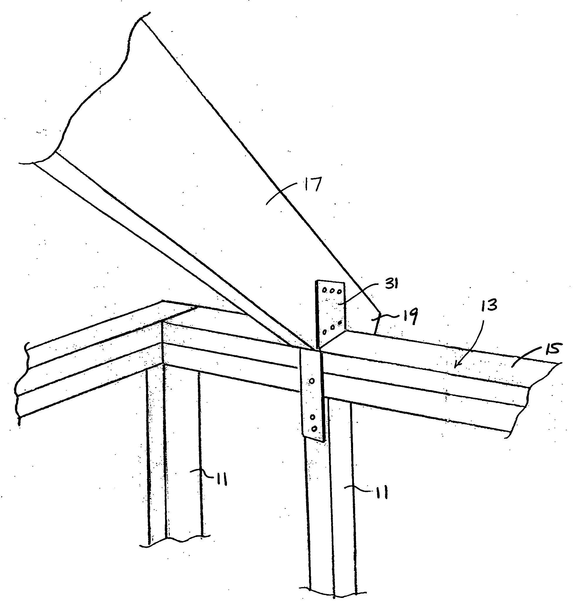
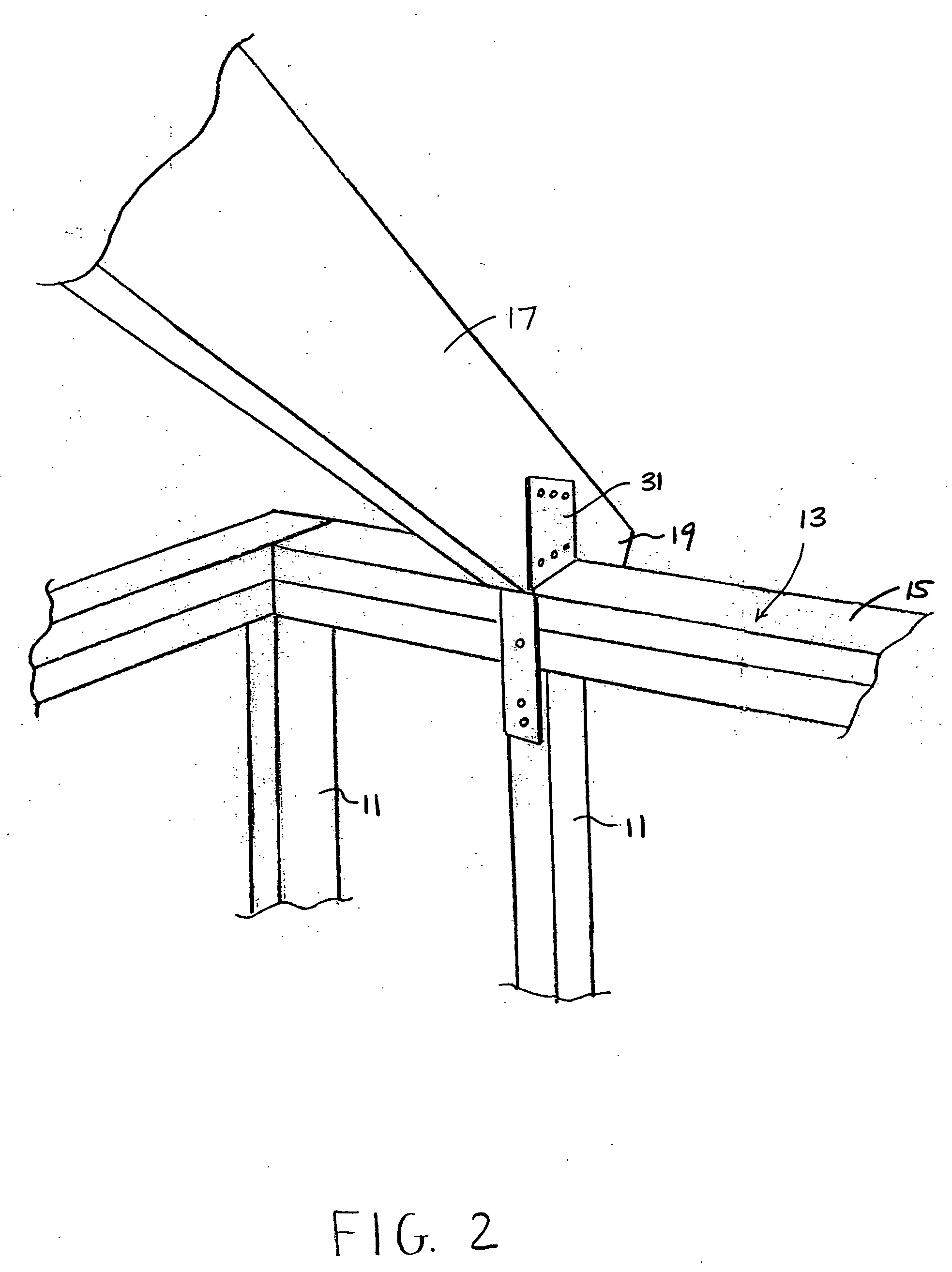
[0025] Referring now to FIG. 2, there is shown a tie which is constructed according to the teachings of the present invention, the tie being identified generally by reference numeral 31. As will be described further in detail below, tie 31 is designed to help secure together a vertically disposed, elongated wooden stud 11, a horizontal top plate 13 (represented herein as being in the form of a pair of stacked 2×4 wooden beams 15) and a rafter 17 (represented herein as being in the form of a single 2×6 wooden beam). Together, stud 11, top plate 13 and rafter 17 partially define the support structure, or framing, for a building.

[0026] Referring now to FIG. 3, there is shown a flat pattern layout, or blank, of tie 31 prior to bending, tie 31 preferably being constructed from a rigid, durable and strong piece of sheet metal, such as an 18 gauge galvanized steel or an 18 gauge 316 stainless steel.

[0027] Tie 31 comprises a rectangularly-shaped base 33 which serves as the main plate for ...


PUM


Abstract

A tie is designed to secure together in a building structure a vertical stud, a top plate disposed horizontally across the top end of the vertical stud and a rafter extending up from the top plate at an acute angle. The tie is constructed from a unitary sheet metal body which is adapted for securement against at least two surfaces of each of the rafter, the top plate and the vertical stud. The unitary sheet metal body for the tie includes a base, a pair of rafter plates which extend orthogonally upward from opposite sides of the base, and a pair of stud tails which extend orthogonally downward from opposite ends of the base. The base together with the pair of rafter plates define a recess that is sized and shaped to fittingly receive a portion of the rafter. In addition, the base together with the pair of stud tails define a channel which is sized and shaped to fittingly receive at least a portion of the top plate and the vertical stud.

Description

CROSS-REFERENCE TO RELATED APPLICATIONS [0001] The present application claims the benefit under 35 U.S.C. 119(e) of U.S. provisional Patent Application Ser. No. 60 / 643,078, filed Jan. 11, 2005, the disclosure of which is incorporated herein by reference.BACKGROUND OF THE INVENTION [0002] The present invention relates generally to the construction of buildings and more particularly to metal ties which are used to connect and structurally reinforce the interconnection of wood framing members in a building structure. [0003] Wood framing members are commonly used in construction to define the structural support for a building. Specifically, as seen most clearly in FIG. 1, the wood framing for a building commonly includes a plurality of vertical studs 11 (each commonly constructed from an elongated wooden beam) which are spaced approximately 16 inches apart from one another in a particular configuration to define the outer periphery of the building. In addition, a top plate 13 (also comm...

Claims


Application Information

Patent Timeline
IPC IPC(8): E04B1/38
CPCE04B1/2608E04B7/045
Inventor DUFAULT, EDDY S.
Owner DUFAULT EDDY S
Why Eureka
Try Eureka