

Compliant Electrical Contact and Assembly
- Summary
- Abstract
- Description
- Claims
- Application Information
AI Technical Summary
Benefits of technology
Problems solved by technology
Method used
Image

Examples
first embodiment
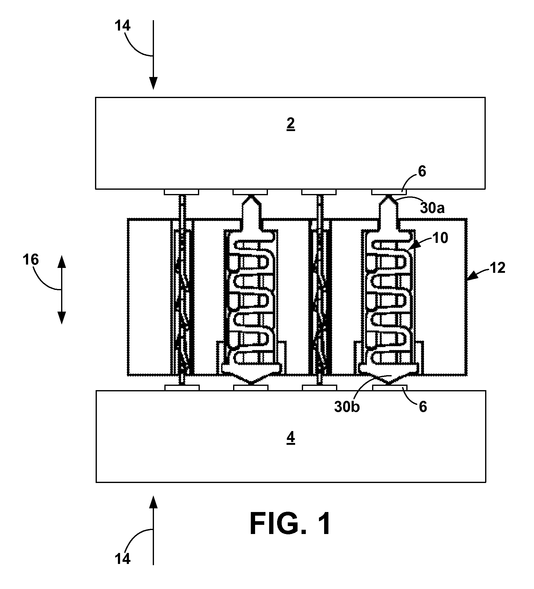
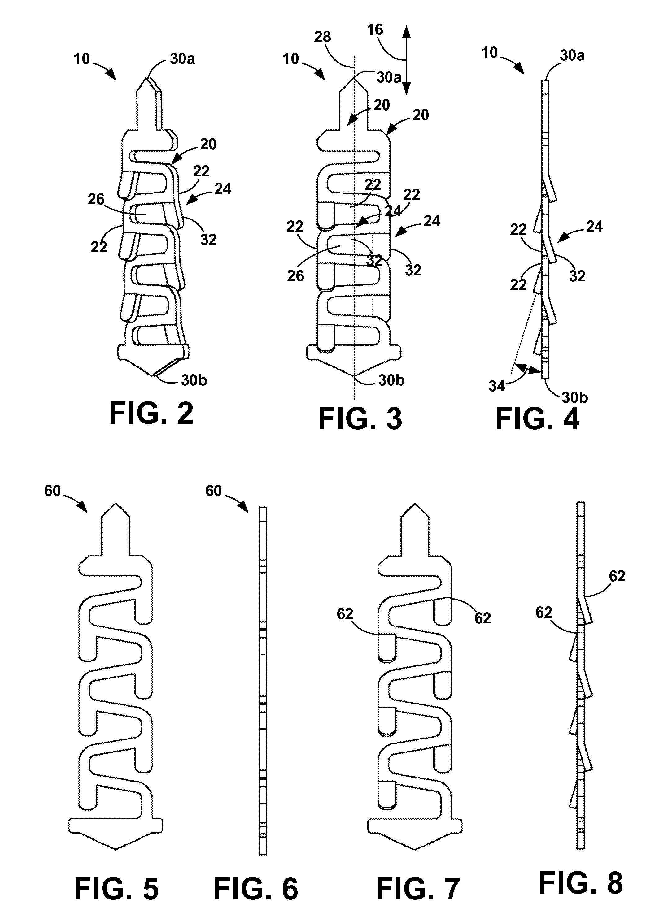
[0095]In the contact of the present invention, the convolutions 22 have appendages 24 which electrically short a convolution 22 to the adjacent convolution 22 throughout at least a significant portion of the compression range of the contact 10, as described below. The appendage 24 may be a distinct component of the convolution 22, that is, it is a portion of the convolution 22 that has no other purpose than to contact the adjacent convolution 22. Such an appendage 24 may be a single finger 32, as in the configuration of FIGS. 2 and 9, or it may consist of a pair of opposed fingers 32a, 32b, as in the configuration of FIGS. 13, 16, and 19. Alternatively, the appendage 24 may be a portion of the convolution 22 that is indistinct, that is, the appendage function is not its only function, as in the configuration of FIG. 24.
[0096]The gap 26 between convolutions 22 can be any size. The greater the length of the appendage 24, the greater the gap 26 may be, the stipulation being that the ap...
second embodiment
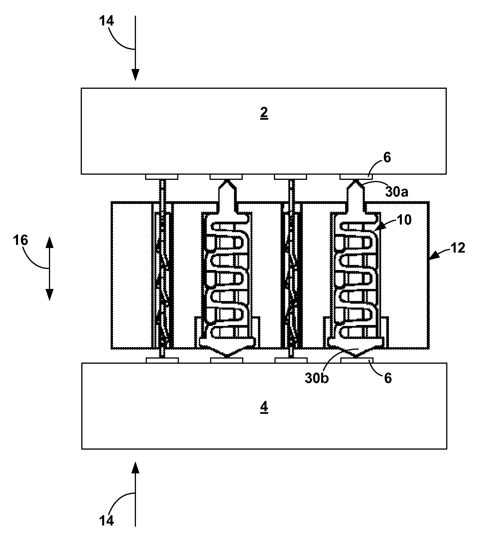
[0107]In the contact 10 of the present invention, shown in FIGS. 36-49, the contact 10 has a shunt 110 that is generally parallel to the spring 20 and that spans the convolutions 22 longitudinally. The shunt 110 is attached at or near one of the contact points 30a and spans most or all of the convolutions, leaving a length 112 that the shunt 110 does not span. The length 112 leaves space for the shunt 110 so that it does not extend all the way to the other contact point 30b at full compression, thereby allowing the contact 10 to compress fully.
[0108]As indicated above, the shunt 110 is attached at or near one of the contact points 30a, as at 114. The present invention contemplates any manner of attachment. In one manner, the contact 10 is stamped as a single unit and bent 180° at the contact point 30a so that the shunt 110 and spring 20 are parallel. In another, shown in FIG. 39, the shunt 110 and spring 20 are stamped as separate components with abutting, interlocking projections 1...
PUM
 Abstract
Description
Claims
Application Information